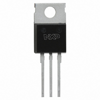
PHE13005,127 NXP Semiconductors, PHE13005,127 Datasheet

PHE13005,127
Specifications of PHE13005,127
PHE13005
PHE13005
Available stocks
Related parts for PHE13005,127
PHE13005,127 Summary of contents
Page 1
PHE13005 Silicon diffused power transistor Rev. 03 — 20 November 2009 1. Product profile 1.1 General description High voltage, high speed NPN planar-passivated power switching transistor in a SOT78 plastic package intended for use in high frequency electronic lighting ballast ...
Page 2
... NXP Semiconductors 2. Ordering information Table 2. Ordering information Type number Package Name Description PHE13005 TO-220AB plastic single-ended package; heatsink mounted; 1 mounting hole; 3-lead TO-220AB 3. Limiting values Table 3. Limiting values In accordance with the Absolute Maximum Rating System (IEC 60134). Symbol Parameter V collector-emitter peak ...
Page 3
... NXP Semiconductors ( CM(max) I C(max) 1 −1 10 −2 10 − Fig 3. Forward bias safe operating area Fig 4. Normalized total power dissipation as a function of heatsink temperature PHE13005_3 Product data sheet duty cycle = 0.01 (1) (3) 10 120 P der (%) 100 150 Rev. 03 — 20 November 2009 PHE13005 Silicon diffused power transistor 001aai071 = 20 μ ...
Page 4
... NXP Semiconductors 4. Thermal characteristics Table 4. Thermal characteristics Symbol Parameter R thermal resistance from th(j-mb) junction to mounting base R thermal resistance from th(j-a) junction to ambient 10 Z th(j-mb) (K/W) δ = 0.5 1 0.2 0.1 0.05 0.02 −1 10 0.01 −2 10 −5 − Fig 5. Transient thermal impedance from junction to mounting base as a function of pulse duration ...
Page 5
... NXP Semiconductors 5. Characteristics Table 5. Characteristics Symbol Parameter Static characteristics I collector-emitter cut-off CES current I collector-base cut-off CBO current I collector-emitter cut-off CEO current I emitter-base cut-off EBO current V collector-emitter CEOsus sustaining voltage V collector-emitter CEsat saturation voltage V base-emitter saturation BEsat voltage h DC current gain FE Dynamic characteristics ...
Page 6
... NXP Semiconductors 100 Ω to 200 Ω horizontal oscilloscope vertical 6 V 300 Ω Fig 6. Test circuit for collector-emitter sustaining voltage 2.0 V CEsat ( 1.6 1.2 0.8 0.4 0 −2 − Fig 8. Collector-emitter saturation voltage; typical values PHE13005_3 Product data sheet I C (mA 250 100 1 Ω ...
Page 7
... NXP Semiconductors 1.4 V BEsat (V) 1.2 1.0 0.8 0.6 0.4 0.2 0 − Fig 10. Base-emitter saturation voltage; typical values Fig 12. Test circuit for resistive load switching PHE13005_3 Product data sheet 003aad541 − (A) C Fig 11. DC current gain as a function of collector current; typical values ...
Page 8
... NXP Semiconductors Bon V BB Fig 14. Test circuit for inductive load switching PHE13005_3 Product data sheet DUT I B 001aab991 Fig 15. Switching times waveforms for inductive load Rev. 03 — 20 November 2009 PHE13005 Silicon diffused power transistor I Con off I Bon t −I Boff 001aab992 © NXP B.V. 2009. All rights reserved. ...
Page 9
... NXP Semiconductors 6. Package outline Plastic single-ended package; heatsink mounted; 1 mounting hole; 3-lead TO-220AB DIMENSIONS (mm are the original dimensions) (2) UNIT 4.7 1.40 0.9 1.6 1.3 mm 4.1 1.25 0.6 1.0 1.0 Notes 1. Lead shoulder designs may vary. 2. Dimension includes excess dambar. OUTLINE VERSION ...
Page 10
... Revision history Document ID Release date PHE13005_3 20091120 • Modifications: The format of this data sheet has been redesigned to comply with the new identity guidelines of NXP Semiconductors. • Legal texts have been adapted to the new company name where appropriate. PHE13005_2 19990201 PHE13005_1 19980801 PHE13005_3 ...
Page 11
... Right to make changes — NXP Semiconductors reserves the right to make changes to information published in this document, including without limitation specifications and product descriptions, at any time and without notice ...
Page 12
... NXP Semiconductors 10. Contents 1 Product profile . . . . . . . . . . . . . . . . . . . . . . . . . . .1 1.1 General description . . . . . . . . . . . . . . . . . . . . . .1 1.2 Features and benefits . . . . . . . . . . . . . . . . . . . . .1 1.3 Applications . . . . . . . . . . . . . . . . . . . . . . . . . . . .1 1.4 Quick reference data . . . . . . . . . . . . . . . . . . . . .1 2 Ordering information . . . . . . . . . . . . . . . . . . . . . .2 3 Limiting values Thermal characteristics . . . . . . . . . . . . . . . . . . .4 5 Characteristics . . . . . . . . . . . . . . . . . . . . . . . . . . .5 6 Package outline . . . . . . . . . . . . . . . . . . . . . . . . . .9 7 Revision history . . . . . . . . . . . . . . . . . . . . . . . . .10 8 Legal information 8.1 Data sheet status . . . . . . . . . . . . . . . . . . . . . . . 11 8 ...


