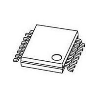
PCF2123TS/1.118 NXP Semiconductors, PCF2123TS/1.118 Datasheet - Page 10

PCF2123TS/1.118
Manufacturer Part Number
PCF2123TS/1.118
Description
Manufacturer
NXP Semiconductors
Datasheet
1.PCF2123TS1.118.pdf
(61 pages)
Specifications of PCF2123TS/1.118
Bus Type
Serial (3-Wire, SPI)
Package Type
TSSOP
Operating Supply Voltage (max)
5.5V
Operating Temperature Classification
Industrial
Operating Temperature (max)
85C
Operating Temperature (min)
-40C
Mounting
Surface Mount
Date Format
DW:DM:M:Y
Time Format
HH:MM:SS
Lead Free Status / RoHS Status
Compliant
NXP Semiconductors
PCF2123
Product data sheet
8.3.1.1 Reset
A reset is automatically generated at power-on. A reset can also be initiated with the
software reset command. It is generally recommended to make a software reset after
power-on.
A software reset can be initiated by setting the bits 6, 4 and 3 in register Control_1 logic 1
and all other bits logic 0 by sending the bit sequence 01011000 (58h), see
bit sequence is not correct, the software reset instruction will be ignored to protect the
device from accidently being reset. When sending the software instruction, the other bits
are not written.
After reset, the following mode is entered:
Fig 7.
•
•
•
•
•
•
32.768 kHz on pin CLKOUT active
24 hour mode is selected
Offset register is set to 0
No alarms set
Timer disabled
No interrupts enabled
(1) When CE is inactive, the interface is reset.
reset signal
internal
Software reset command
SCL
CE
All information provided in this document is subject to legal disclaimers.
R/W
b7
0
b6
0
Rev. 03 — 5 October 2010
b5
0
b4
1
b3
0
addr 00
b2
0
b1
HEX
0
b0
0
b7
0
b6
1
software reset 58
b5
0
b4
1
SPI Real time clock/calendar
b3
1
b2
HEX
0
b1
0
PCF2123
b0
© NXP B.V. 2010. All rights reserved.
0
Figure
001aai562
(1)
7. If this
10 of 61


