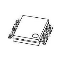
PCA2125TS/1-T NXP Semiconductors, PCA2125TS/1-T Datasheet - Page 13

PCA2125TS/1-T
Manufacturer Part Number
PCA2125TS/1-T
Description
Real Time Clock AUTO RL TME CLCK/CAL
Manufacturer
NXP Semiconductors
Datasheet
1.PCA2125TS1-T.pdf
(36 pages)
Specifications of PCA2125TS/1-T
Bus Type
Serial (3-Wire, SPI)
Package Type
TSSOP
Operating Supply Voltage (max)
5.5V
Operating Temperature (min)
-40C
Mounting
Surface Mount
Date Format
DW:DM:M:Y
Time Format
HH:MM:SS
Mounting Style
SMD/SMT
Package / Case
TSSOP-14
Lead Free Status / RoHS Status
Compliant
Other names
PCA2125TS/1,118
NXP Semiconductors
Table 25.
PCA2125_1
Product data sheet
Bit
7 to 0 COUNTDOWN_TIMER[7:0]
Symbol
Register Countdown_timer (address 0Fh) bit description
8.6.1 Second and minute interrupt
8.6 Timer functions
To prevent the timer flags being overwritten while clearing bit AF, a logic AND is performed
during a write access. The flag is reset by writing a logic 0 but its value is not affected by
writing a logic 1.
Table 22.
Table 23
bit TF are unaffected.
Table 23.
The countdown timer has four selectable source clocks allowing for countdown periods in
the range from less than 1 ms to more than 4 hours. There are also two pre-defined timers
which can be used to generate an interrupt once per second or once per minute.
Registers Control_2 (01h), Timer_control (0Eh) and Countdown_timer (0Fh) are used to
control the timer function and output.
Table 24.
The second and minute interrupts (bits SI and MI) are pre-defined timers for generating
periodic interrupts. The timers can be enabled independently of one another, however a
minute interrupt enabled on top of a second interrupt will not be distinguishable since it will
occur at the same time; see
Register
Control_2
Register
Control_2
Bit
7
6 to 2
1 to 0
shows what instruction must be sent to clear bit AF. In this example, bit MSF and
Symbol
TE
-
CTD[1:0]
Flag location in register Control_2
Example to clear only AF (bit 3) in register Control_2
Register Timer_control (address 0Eh) bit description
Value
00h to FFh
Bit 7
-
Bit 7
-
Value
0
1
0
00
01
10
11
Rev. 01 — 28 July 2008
Bit 6
-
Bit 6
-
Description
countdown value = n.
CountdownPeriod
Figure
Description
countdown timer is disabled
countdown timer is enabled
unused
4096 Hz countdown timer source clock
64 Hz countdown timer source clock
1 Hz countdown timer source clock
1
60
Bit 5
MSF
Bit 5
1
Hz countdown timer source clock
9.
Bit 4
-
Bit 4
-
=
-------------------------------------------------------------- -
SourceClockFrequency
Bit 3
AF
Bit 3
0
n
SPI Real-time clock/calendar
Bit 2
TF
Bit 2
1
PCA2125
© NXP B.V. 2008. All rights reserved.
Bit 1
-
Bit 1
-
Reference
Section 8.6.2
Reference
Section 8.6.2
Bit 0
-
Bit 0
-
13 of 36


