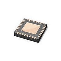
ISP1504ABS,118 NXP Semiconductors, ISP1504ABS,118 Datasheet - Page 53

ISP1504ABS,118
Manufacturer Part Number
ISP1504ABS,118
Description
RF Transceiver USB ULPI TRANSCEIVER
Manufacturer
NXP Semiconductors
Datasheet
1.ISP1504ABS118.pdf
(83 pages)
Specifications of ISP1504ABS,118
Number Of Transceivers
1
Esd Protection
YeskV
Operating Supply Voltage (typ)
Not RequiredV
Operating Temperature Classification
Industrial
Operating Supply Voltage (max)
Not RequiredV
Operating Supply Voltage (min)
Not RequiredV
Pin Count
32
Mounting
Surface Mount
Operating Temperature (max)
85C
Operating Temperature (min)
-40C
Operating Supply Voltage
1.65 V to 3.6 V
Mounting Style
SMD/SMT
Package / Case
HVQFN-32
Lead Free Status / RoHS Status
Compliant
Other names
935278308118 ISP1504ABS-T
NXP Semiconductors
Table 31.
Table 32.
Table 33.
Table 34.
ISP1504A_ISP1504C_3
Product data sheet
Bit
Symbol
Reset
Access
Bit
7 to 5 -
4
3
2
1
0
Bit
Symbol
Reset
Access
Bit
7 to 5 -
4
3
Symbol
ID_GND_R
SESS_END_R
SESS_VALID_R
VBUS_VALID_R
HOST_DISCON_R Host Disconnect Rise: Enables interrupts and RXCMDs for logic 0 to logic 1 transitions on
Symbol
ID_GND_F
SESS_END_F
USB Interrupt Enable Rising Edge register (address R = 0Dh to 0Fh, W = 0Dh, S = 0Eh, C = 0Fh) bit
allocation
USB Interrupt Enable Rising Edge register (address R = 0Dh to 0Fh, W = 0Dh, S = 0Eh, C = 0Fh) bit
description
USB Interrupt Enable Falling Edge register (address R = 10h to 12h, W = 10h, S = 11h, C = 12h) bit
allocation
USB Interrupt Enable Falling Edge register (address R = 10h to 12h, W = 10h, S = 11h, C = 12h) bit
description
10.1.5 USB Interrupt Enable Rising Edge register
10.1.6 USB Interrupt Enable Falling Edge register
R/W/S/C
R/W/S/C
7
0
7
0
The bits in this register enable interrupts and RXCMDs to be sent when the corresponding
bits in the USB Interrupt Status register change from logic 0 to logic 1. By default, all
transitions are enabled.
The bits in this register enable interrupts and RXCMDs to be sent when the corresponding
bits in the USB Interrupt Status register change from logic 1 to logic 0. By default, all
transitions are enabled. See
Description
reserved
ID Ground Rise: Enables interrupts and RXCMDs for logic 0 to logic 1 transitions on ID_GND.
Session End Rise: Enables interrupts and RXCMDs for logic 0 to logic 1 transitions on
SESS_END.
Session Valid Rise: Enables interrupts and RXCMDs for logic 0 to logic 1 transitions on
SESS_VLD.
V
A_VBUS_VLD.
HOST_DISCON.
Description
reserved
ID Ground Fall: Enables interrupts and RXCMDs for logic 1 to logic 0 transitions on ID_GND.
Session End Fall: Enables interrupts and RXCMDs for logic 1 to logic 0 transitions on
SESS_END.
reserved
R/W/S/C
reserved
R/W/S/C
BUS
6
0
6
0
Valid Rise: Enables interrupts and RXCMDs for logic 0 to logic 1 transitions on
R/W/S/C
R/W/S/C
5
0
5
0
Rev. 03 — 7 April 2008
Table 31
ID_GND_R
ID_GND_F
Table
R/W/S/C
R/W/S/C
4
1
4
1
shows the bit allocation of the register.
33.
R/W/S/C
R/W/S/C
END_R
SESS_
SESS_
END_F
3
1
3
1
ISP1504A; ISP1504C
VALID_R
VALID_F
R/W/S/C
R/W/S/C
SESS_
SESS_
ULPI HS USB OTG transceiver
2
1
2
1
VALID_R
VALID_F
R/W/S/C
R/W/S/C
VBUS_
VBUS_
1
1
1
1
© NXP B.V. 2008. All rights reserved.
DISCON_R
DISCON_F
R/W/S/C
R/W/S/C
HOST_
HOST_
0
1
0
1
52 of 82


