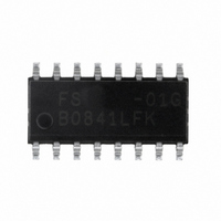
FS6370-01G-XTD ON Semiconductor, FS6370-01G-XTD Datasheet - Page 12

FS6370-01G-XTD
Manufacturer Part Number
FS6370-01G-XTD
Description
IC CLOCK GEN 3-PLL EEPROM 16SOIC
Manufacturer
ON Semiconductor
Type
PLL Clock Generatorr
Datasheet
1.FS6370-01G-XTD.pdf
(28 pages)
Specifications of FS6370-01G-XTD
Pll
Yes
Input
Crystal
Output
CMOS
Number Of Circuits
1
Ratio - Input:output
1:4
Differential - Input:output
No/No
Frequency - Max
230MHz
Divider/multiplier
Yes/No
Voltage - Supply
3 V ~ 5.5 V
Operating Temperature
0°C ~ 70°C
Mounting Type
Surface Mount
Package / Case
16-SOIC (3.9mm Width)
Frequency-max
230MHz
Mounting Style
SMD/SMT
Max Input Freq
230 MHz
Max Output Freq
27 MHz
Number Of Outputs
1
Operating Supply Voltage
5 V to 3.3 V
Operating Temperature Range
0 C to + 70 C
Supply Current
43 mA
Lead Free Status / RoHS Status
Lead free / RoHS Compliant
Other names
766-1025
Available stocks
Company
Part Number
Manufacturer
Quantity
Price
Company:
Part Number:
FS6370-01G-XTD
Manufacturer:
ON Semiconductor
Quantity:
38
FS6370
9.0 Programming Information
Table 3: Register Map (Note: All register bits are cleared to zero on power-up)
9.1 Control Bit Assignments
If any PLL control bit is altered during device operation, including those bits controlling the reference and feedback dividers, the output
frequency will slew smoothly (in a glitch-free manner) to the new frequency. The slew rate is related to the programmed loop filter time
constant.
However, any programming changes to any mux or post divider control bits will cause a glitch on an operating clock output.
9.1.1. Power-Down
All power-down functions are controlled by enable bits. That is, the bits select which portions of the FS6370 to power-down when the
PD input is asserted. If the power-down bit contains a one, the related circuit will shut down if the PD pin is high (run mode only). When
the PD pin is low, power is enabled to all circuits.
If the power-down bit contains a zero, the related circuit will continue to function regardless of the PD pin state.
Address
Byte 15
Byte 14
Byte 13
Byte 12
Byte 11
Byte 10
Byte 9
Byte 8
Byte 7
Byte 6
Byte 5
Byte 4
Byte 3
Byte 2
Byte 1
Byte 0
(selected via SEL_CD = 1)
(selected via SEL_CD = 0)
(selected via SEL_CD = 0)
Bit 7
MUX_D2[1:0]
MUX_D1[1:0]
MUX_C1[1:0]
MUX_B[1:0]
MUX_A[1:0]
(selected via SEL_CD = 1)
(selected via SEL_CD = 0)
Bit 6
POST_D2[3:0]
POST_D1[3:0]
POST_B[3:0]
(selected via SEL_CD pin = 1)
FBKDIV_C2[7:3] M-Counter
FBKDIV_C1[7:3] M-Counter
FBKDIV_B[7:3] M-Counter
FBKDIV_A[7:3] M-Counter
(selected via SEL_CD = 0
Reserved (0)
PDPLL_C
PDPLL_B
PDPLL_A
(selected via SEL_CD = 1)
Bit 5
Rev. 3 | Page 12 of 28 | www.onsemi.com
MUX_C2[1:0]
(SEL_CD=1)
(SEL_CD=0)
LFTC_C2
LFTC_C1
(selected via SEL_CD pin = 1)
LFTC_B
LFTC_A
(selected via SEL_CD = 0)
Bit 4
REFDIV_C2[7:0]
REFDIV_C1[7:0]
REFDIV_B[7:0]
REFDIV_A[7:0]
(SEL_CD=1)
(SEL_CD=0)
PDPOST_D
CP_C2
CP_C1
CP_B
CP_A
Bit 3
PDPOST_C
(selected via SEL_CD = 1)
(selected via SEL_CD = 0)
Bit 2
POST_C2[3:0]
POST_C1[3:0]
POST_A[3:0]
(selected via SEL_CD pin = 1)
(selected via SEL_CD pin =
FBKDIV_C2[10:8] M-Counter
FBKDIV_C1[10:8] M-Counter
FBKDIV_B[10:8] M-Counter
FBKDIV_A[10:8] M-Counter
FBKDIV_C2[2:0] A-Counter
FBKDIV_C1[2:0] A-Counter
(selected via SEL_CD = 0)
(selected via SEL_CD = 1)
FBKDIV_B[2:0] A-Counter
FBKDIV_A[2:0] A-Counter
PDPOST_B
Bit 1
PDPOST_A
1)
Bit 0


