CS82C54 Intersil, CS82C54 Datasheet - Page 13
CS82C54
Manufacturer Part Number
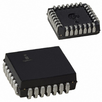
CS82C54
Description
IC TIMER PROG CMOS 8MHZ 28-PLCC
Manufacturer
Intersil
Type
Programmable Timerr
Specifications of CS82C54
Frequency
8MHz
Voltage - Supply
4.5 V ~ 5.5 V
Current - Supply
10mA
Operating Temperature
0°C ~ 70°C
Package / Case
28-PLCC
Peak Reflow Compatible (260 C)
No
Leaded Process Compatible
No
Mounting Type
Surface Mount
Rohs Compliant
No
Number Of Leads
28
Operating Frequency
8 MHz
Package Type
PLCC
Power, Standby
5 V
Technology
CMOS
Lead Free Status / RoHS Status
Contains lead / RoHS non-compliant
Count
-
Available stocks
Company
Part Number
Manufacturer
Quantity
Price
Company:

Part Number:
CS82C54
Manufacturer:
HAR/INT
Quantity:
5 380
Company:
Part Number:
CS82C54
Manufacturer:
HAR/INT
Quantity:
5 380
Part Number:
CS82C54
Manufacturer:
INTERSIL
Quantity:
20 000
Company:
Part Number:
CS82C54-10
Manufacturer:
HAR/INT
Quantity:
8 000
Company:
Part Number:
CS82C54-10
Manufacturer:
HAR/INT
Quantity:
8 000
Part Number:
CS82C54-10
Manufacturer:
INTERSIL
Quantity:
20 000


MODE 2: RATE GENERATOR
This Mode functions like a divide-by-N counter. It is typically
used to generate a Real Time Clock Interrupt. OUT will
initially be high. When the initial count has decremented to 1,
OUT goes low for one CLK pulse. OUT then goes high
again, the Counter reloads the initial count and the process
is repeated. Mode 2 is periodic; the same sequence is
repeated indefinitely. For an initial count of N, the sequence
repeats every N CLK cycles.
GATE = 1 enables counting; GATE = 0 disables counting. If
GATE goes low during an output pulse, OUT is set high
immediately. A trigger reloads the Counter with the initial
count on the next CLK pulse; OUT goes low N CLK pulses
after the trigger. Thus the GATE input can be used to
synchronize the Counter.
After writing a Control Word and initial count, the Counter will
be loaded on the next CLK pulse. OUT goes low N CLK
pulses after the initial count is written. This allows the
Counter to be synchronized by software also.
Writing a new count while counting does not affect the current
counting sequence. If a trigger is received after writing a new
count but before the end of the current period, the Counter will
be loaded with the new count on the next CLK pulse and
counting will continue from the end of the current counting
cycle.
GATE
GATE
GATE
CLK
OUT
CLK
OUT
CLK
OUT
WR
WR
WR
CW = 14
CW = 14
CW = 14
N
N
N
N
N
N
LSB = 3
LSB = 4
LSB = 3
N
N
N
FIGURE 11. MODE 2
N
N
N
0
3
0
3
0
4
13
LSB = 5
0
2
0
2
0
3
0
1
0
2
0
2
0
3
0
1
0
3
0
2
0
2
0
5
0
1
0
1
0
4
0
3
0
3
0
3
82C54
MODE 3: SQUARE WAVE MODE
Mode 3 is typically used for Baud rate generation. Mode 3 is
similar to Mode 2 except for the duty cycle of OUT. OUT will
initially be high. When half the initial count has expired, OUT
goes low for the remainder of the count. Mode 3 is periodic;
the sequence above is repeated indefinitely. An initial count
of N results in a square wave with a period of N CLK cycles.
GATE = 1 enables counting; GATE = 0 disables counting. If
GATE goes low while OUT is low, OUT is set high
immediately; no CLK pulse is required. A trigger reloads the
Counter with the initial count on the next CLK pulse. Thus
the GATE input can be used to synchronize the Counter.
After writing a Control Word and initial count, the Counter will
be loaded on the next CLK pulse. This allows the Counter to
be synchronized by software also.
Writing a new count while counting does not affect the
current counting sequence. If a trigger is received after
writing a new count but before the end of the current half-
cycle of the square wave, the Counter will be loaded with the
new count on the next CLK pulse and counting will continue
from the new count. Otherwise, the new count will be loaded
at the end of the current half-cycle.
GATE
GATE
GATE
CLK
OUT
CLK
OUT
CLK
OUT
WR
WR
WR
CW = 16 LSB = 4
CW = 16 LSB = 5
CW = 16 LSB = 4
N
N
N
N
N
N
N
N
N
N
N
N
FIGURE 12. MODE 3
0
4
0
5
0
4
0
2
0
4
0
2
0
4
0
2
0
4
0
2
0
5
0
2
0
2
0
2
0
4
0
2
0
5
0
2
0
4
0
4
0
4
0
2
0
2
0
2
0
4
0
5
0
4
0
2
0
2
0
2
Related parts for CS82C54
Image
Part Number
Description
Manufacturer
Datasheet
Request
R

Part Number:
Description:
Standard Clock Oscillators 156.250MHz 2.5Volt 50ppm -10C +70C
Manufacturer:
TXC Corporation
Datasheet:
Part Number:
Description:
Standard Clock Oscillators 312.500MHz 3.3Volt 50ppm -10C +70C
Manufacturer:
TXC Corporation
Datasheet:
Part Number:
Description:
Standard Clock Oscillators 425.000MHz 2.5Volt 50ppm -10C +70C
Manufacturer:
TXC Corporation
Datasheet:
Part Number:
Description:
Standard Clock Oscillators 78.125MHz 2.5Volt 50ppm -10C +70C
Manufacturer:
TXC Corporation
Datasheet:
Part Number:
Description:
Standard Clock Oscillators 156.250MHz 3.3Volt 50ppm -10C +70C
Manufacturer:
TXC Corporation
Datasheet:
Part Number:
Description:
Standard Clock Oscillators 156.250MHz 2.5Volt 100ppm -10C +70C
Manufacturer:
TXC Corporation
Datasheet:
Part Number:
Description:
Standard Clock Oscillators 312.500MHz 3.3Volt 100ppm -10C +70C
Manufacturer:
TXC Corporation
Datasheet:
Part Number:
Description:
Standard Clock Oscillators 212.500MHz 3.3Volt 100ppm -10C +70C
Manufacturer:
TXC Corporation
Datasheet:
Part Number:
Description:
Standard Clock Oscillators 312.500MHz 2.5Volt 100ppm -10C +70C
Manufacturer:
TXC Corporation
Datasheet:
Part Number:
Description:
Standard Clock Oscillators 425.000MHz 2.5Volt 100ppm -10C +70C
Manufacturer:
TXC Corporation
Datasheet:
Part Number:
Description:
Standard Clock Oscillators 106.250MHz 3.3Volt 50ppm -10C +70C
Manufacturer:
TXC Corporation
Datasheet:
Part Number:
Description:
Standard Clock Oscillators 78.125MHz 2.5Volt 100ppm -10C +70C
Manufacturer:
TXC Corporation
Datasheet:
Part Number:
Description:
Standard Clock Oscillators 156.250MHz 3.3Volt 100ppm -10C +70C
Manufacturer:
TXC Corporation
Datasheet:
Part Number:
Description:
Standard Clock Oscillators 212.500MHz 2.5Volt 100ppm -10C +70C
Manufacturer:
TXC Corporation
Datasheet:
Part Number:
Description:
Standard Clock Oscillators 425.000MHz 3.3Volt 100ppm -10C +70C
Manufacturer:
TXC Corporation
Datasheet: