CS82C54 Intersil, CS82C54 Datasheet - Page 3
CS82C54
Manufacturer Part Number
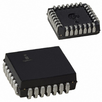
CS82C54
Description
IC TIMER PROG CMOS 8MHZ 28-PLCC
Manufacturer
Intersil
Type
Programmable Timerr
Specifications of CS82C54
Frequency
8MHz
Voltage - Supply
4.5 V ~ 5.5 V
Current - Supply
10mA
Operating Temperature
0°C ~ 70°C
Package / Case
28-PLCC
Peak Reflow Compatible (260 C)
No
Leaded Process Compatible
No
Mounting Type
Surface Mount
Rohs Compliant
No
Number Of Leads
28
Operating Frequency
8 MHz
Package Type
PLCC
Power, Standby
5 V
Technology
CMOS
Lead Free Status / RoHS Status
Contains lead / RoHS non-compliant
Count
-
Available stocks
Company
Part Number
Manufacturer
Quantity
Price
Company:

Part Number:
CS82C54
Manufacturer:
HAR/INT
Quantity:
5 380
Company:
Part Number:
CS82C54
Manufacturer:
HAR/INT
Quantity:
5 380
Part Number:
CS82C54
Manufacturer:
INTERSIL
Quantity:
20 000
Company:
Part Number:
CS82C54-10
Manufacturer:
HAR/INT
Quantity:
8 000
Company:
Part Number:
CS82C54-10
Manufacturer:
HAR/INT
Quantity:
8 000
Part Number:
CS82C54-10
Manufacturer:
INTERSIL
Quantity:
20 000


Absolute Maximum Ratings
Supply Voltage . . . . . . . . . . . . . . . . . . . . . . . . . . . . . . . . . . . . . +8.0V
Input, Output or I/O Voltage . . . . . . . . . . . . GND-0.5V to V
ESD Classification . . . . . . . . . . . . . . . . . . . . . . . . . . . . . . . . . Class 1
Operating Conditions
Operating Voltage Range. . . . . . . . . . . . . . . . . . . . . . +4.5V to +5.5V
Operating Temperature Range
CAUTION: Stresses above those listed in “Absolute Maximum Ratings” may cause permanent damage to the device. This is a stress only rating and operation of the
device at these or any other conditions above those indicated in the operational sections of this specification is not implied.
DC Electrical Specifications
Capacitance
NOTE:
VIH
VIL
VOH
VOL
II
IO
ICCSB
ICCOP
1. Not tested, but characterized at initial design and at major process/design changes.
CX82C54 . . . . . . . . . . . . . . . . . . . . . . . . . . . . . . . . . 0
IX82C54 . . . . . . . . . . . . . . . . . . . . . . . . . . . . . . . . -40
MD82C54 . . . . . . . . . . . . . . . . . . . . . . . . . . . . . . -55
SYMBOL
SYMBOL
COUT
CI/O
CIN
Logical One Input Voltage
Logical Zero Input Voltage
Operating Power Supply Current
Output HIGH Voltage
Output LOW Voltage
Input Leakage Current
Output Leakage Current
Standby Power Supply Current
T
A
= +25
Input Capacitance
Output Capacitance
I/O Capacitance
PARAMETER
o
C; All Measurements Referenced to Device GND, Note 1
3
PARAMETER
V
CC
= +5.0V ± 10%, Includes all Temperature Ranges
o
C to +125
o
o
C to +70
C to +85
V
CC
CC
MIN
2.0
2.2
3.0
-10
-1
+0.5V
-
-
-
-
-0.4
o
o
o
C
C
C
82C54
TYP
20
20
20
Thermal Information
Thermal Resistance (Typical)
Storage Temperature Range . . . . . . . . . . . . . . . . . -65
Maximum Junction Temperature Ceramic Package. . . . . . . .+175
Maximum Junction Temperature Plastic Package . . . . . . . . .+150
Maximum Lead Temperature Package (Soldering 10s). . . . .+300
*Pb-free PDIPs can be used for through hole wave solder
processing only. They are not intended for use in Reflow solder
processing applications.
Die Characteristics
Gate Count . . . . . . . . . . . . . . . . . . . . . . . . . . . . . . . . . . .2250 Gates
MAX
+10
0.8
0.4
+1
10
10
CERDIP Package. . . . . . . . . . . . . . . . .
CLCC Package. . . . . . . . . . . . . . . . . . .
PDIP Package*. . . . . . . . . . . . . . . . . . .
PLCC Package. . . . . . . . . . . . . . . . . . .
(PLCC - Lead Tips Only)
-
-
-
-
UNITS
pF
pF
pF
UNITS
mA
µA
µA
µA
V
V
V
V
V
V
FREQ = 1MHz
FREQ = 1MHz
FREQ = 1MHz
V
CX82C54, IX82C54
MD82C54
-
IOH = -2.5mA
IOH = -100µA
IOL = +2.5mA
VIN = GND or V
DIP Pins 9,11,14-16,18-23
VOUT = GND or V
DIP Pins 1-8
V
Outputs Open, Counters
Programmed
CLK0 = CLK1 = CLK2 = 8MHz,
VIN = GND or V
Outputs Open
CC
CC
= 5.5V, VIN = GND or V
= 5.5V,
TEST CONDITIONS
TEST CONDITIONS
θ
JA
(
55
65
55
60
o
CC
CC
C/W)
CC
,
o
C to +150
θ
JC
N/A
N/A
(
12
14
CC
o
C/W)
,
o
o
o
o
C
C
C
C
Related parts for CS82C54
Image
Part Number
Description
Manufacturer
Datasheet
Request
R

Part Number:
Description:
Standard Clock Oscillators 156.250MHz 2.5Volt 50ppm -10C +70C
Manufacturer:
TXC Corporation
Datasheet:
Part Number:
Description:
Standard Clock Oscillators 312.500MHz 3.3Volt 50ppm -10C +70C
Manufacturer:
TXC Corporation
Datasheet:
Part Number:
Description:
Standard Clock Oscillators 425.000MHz 2.5Volt 50ppm -10C +70C
Manufacturer:
TXC Corporation
Datasheet:
Part Number:
Description:
Standard Clock Oscillators 78.125MHz 2.5Volt 50ppm -10C +70C
Manufacturer:
TXC Corporation
Datasheet:
Part Number:
Description:
Standard Clock Oscillators 156.250MHz 3.3Volt 50ppm -10C +70C
Manufacturer:
TXC Corporation
Datasheet:
Part Number:
Description:
Standard Clock Oscillators 156.250MHz 2.5Volt 100ppm -10C +70C
Manufacturer:
TXC Corporation
Datasheet:
Part Number:
Description:
Standard Clock Oscillators 312.500MHz 3.3Volt 100ppm -10C +70C
Manufacturer:
TXC Corporation
Datasheet:
Part Number:
Description:
Standard Clock Oscillators 212.500MHz 3.3Volt 100ppm -10C +70C
Manufacturer:
TXC Corporation
Datasheet:
Part Number:
Description:
Standard Clock Oscillators 312.500MHz 2.5Volt 100ppm -10C +70C
Manufacturer:
TXC Corporation
Datasheet:
Part Number:
Description:
Standard Clock Oscillators 425.000MHz 2.5Volt 100ppm -10C +70C
Manufacturer:
TXC Corporation
Datasheet:
Part Number:
Description:
Standard Clock Oscillators 106.250MHz 3.3Volt 50ppm -10C +70C
Manufacturer:
TXC Corporation
Datasheet:
Part Number:
Description:
Standard Clock Oscillators 78.125MHz 2.5Volt 100ppm -10C +70C
Manufacturer:
TXC Corporation
Datasheet:
Part Number:
Description:
Standard Clock Oscillators 156.250MHz 3.3Volt 100ppm -10C +70C
Manufacturer:
TXC Corporation
Datasheet:
Part Number:
Description:
Standard Clock Oscillators 212.500MHz 2.5Volt 100ppm -10C +70C
Manufacturer:
TXC Corporation
Datasheet:
Part Number:
Description:
Standard Clock Oscillators 425.000MHz 3.3Volt 100ppm -10C +70C
Manufacturer:
TXC Corporation
Datasheet: