CS82C54 Intersil, CS82C54 Datasheet - Page 22
CS82C54
Manufacturer Part Number
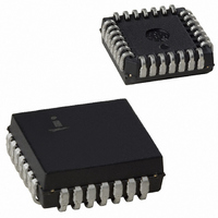
CS82C54
Description
IC TIMER PROG CMOS 8MHZ 28-PLCC
Manufacturer
Intersil
Type
Programmable Timerr
Specifications of CS82C54
Frequency
8MHz
Voltage - Supply
4.5 V ~ 5.5 V
Current - Supply
10mA
Operating Temperature
0°C ~ 70°C
Package / Case
28-PLCC
Peak Reflow Compatible (260 C)
No
Leaded Process Compatible
No
Mounting Type
Surface Mount
Rohs Compliant
No
Number Of Leads
28
Operating Frequency
8 MHz
Package Type
PLCC
Power, Standby
5 V
Technology
CMOS
Lead Free Status / RoHS Status
Contains lead / RoHS non-compliant
Count
-
Available stocks
Company
Part Number
Manufacturer
Quantity
Price
Company:

Part Number:
CS82C54
Manufacturer:
HAR/INT
Quantity:
5 380
Company:
Part Number:
CS82C54
Manufacturer:
HAR/INT
Quantity:
5 380
Part Number:
CS82C54
Manufacturer:
INTERSIL
Quantity:
20 000
Company:
Part Number:
CS82C54-10
Manufacturer:
HAR/INT
Quantity:
8 000
Company:
Part Number:
CS82C54-10
Manufacturer:
HAR/INT
Quantity:
8 000
Part Number:
CS82C54-10
Manufacturer:
INTERSIL
Quantity:
20 000


SEATING
Ceramic Dual-In-Line Frit Seal Packages (CERDIP)
NOTES:
Intersil products are sold by description only. Intersil Corporation reserves the right to make changes in circuit design, software and/or specifications at any time without
notice. Accordingly, the reader is cautioned to verify that data sheets are current before placing orders. Information furnished by Intersil is believed to be accurate and
reliable. However, no responsibility is assumed by Intersil or its subsidiaries for its use; nor for any infringements of patents or other rights of third parties which may result
from its use. No license is granted by implication or otherwise under any patent or patent rights of Intersil or its subsidiaries.
10. Controlling dimension: INCH.
PLANE
PLANE
1. Index area: A notch or a pin one identification mark shall be locat-
2. The maximum limits of lead dimensions b and c or M shall be
3. Dimensions b1 and c1 apply to lead base metal only. Dimension
4. Corner leads (1, N, N/2, and N/2+1) may be configured with a
5. This dimension allows for off-center lid, meniscus, and glass
6. Dimension Q shall be measured from the seating plane to the
7. Measure dimension S1 at all four corners.
8. N is the maximum number of terminal positions.
9. Dimensioning and tolerancing per ANSI Y14.5M - 1982.
BASE
ccc
S1
b2
ed adjacent to pin one and shall be located within the shaded
area shown. The manufacturer’s identification shall not be used
as a pin one identification mark.
measured at the centroid of the finished lead surfaces, when
solder dip or tin plate lead finish is applied.
M applies to lead plating and finish thickness.
partial lead paddle. For this configuration dimension b3 replaces
dimension b2.
overrun.
base plane.
M
C A - B
b
bbb
All Intersil U.S. products are manufactured, assembled and tested utilizing ISO9000 quality systems.
S
S
C A - B
D
A
-A-
-B-
Intersil Corporation’s quality certifications can be viewed at www.intersil.com/design/quality
A
D
e
S
For information regarding Intersil Corporation and its products, see www.intersil.com
S
22
D
-C-
S
-D-
E
Q
aaa
A
L
M
M
c1
e
A/2
C A - B
SECTION A-A
LEAD FINISH
METAL
BASE
(b)
b1
α
S
M
e
A
c
D
S
(c)
82C54
F24.6
24 LEAD CERAMIC DUAL-IN-LINE FRIT SEAL PACKAGE
SYMBOL
eA/2
aaa
bbb
ccc
eA
S1
b1
b2
b3
c1
Q
M
A
D
E
α
N
b
c
e
L
MIL-STD-1835 GDIP1-T24 (D-3, CONFIGURATION A)
0.014
0.014
0.045
0.023
0.008
0.008
0.500
0.120
0.015
0.005
MIN
90
-
-
-
-
-
-
0.100 BSC
0.600 BSC
0.300 BSC
o
INCHES
24
0.225
0.026
0.023
0.065
0.045
0.018
0.015
1.290
0.610
0.200
0.075
0.015
0.030
0.010
0.0015
MAX
105
-
o
12.70
0.36
0.36
1.14
0.58
0.20
0.20
3.05
0.38
0.13
MIN
MILLIMETERS
90
-
-
-
-
-
-
15.24 BSC
o
2.54 BSC
7.62 BSC
24
32.77
15.49
5.72
0.66
0.58
1.65
1.14
0.46
0.38
5.08
1.91
0.38
0.76
0.25
0.038
MAX
105
-
o
Rev. 0 4/94
NOTES
2, 3
2
3
4
2
3
5
5
6
7
8
-
-
-
-
-
-
-
-
-
-
Related parts for CS82C54
Image
Part Number
Description
Manufacturer
Datasheet
Request
R

Part Number:
Description:
Standard Clock Oscillators 156.250MHz 2.5Volt 50ppm -10C +70C
Manufacturer:
TXC Corporation
Datasheet:
Part Number:
Description:
Standard Clock Oscillators 312.500MHz 3.3Volt 50ppm -10C +70C
Manufacturer:
TXC Corporation
Datasheet:
Part Number:
Description:
Standard Clock Oscillators 425.000MHz 2.5Volt 50ppm -10C +70C
Manufacturer:
TXC Corporation
Datasheet:
Part Number:
Description:
Standard Clock Oscillators 78.125MHz 2.5Volt 50ppm -10C +70C
Manufacturer:
TXC Corporation
Datasheet:
Part Number:
Description:
Standard Clock Oscillators 156.250MHz 3.3Volt 50ppm -10C +70C
Manufacturer:
TXC Corporation
Datasheet:
Part Number:
Description:
Standard Clock Oscillators 156.250MHz 2.5Volt 100ppm -10C +70C
Manufacturer:
TXC Corporation
Datasheet:
Part Number:
Description:
Standard Clock Oscillators 312.500MHz 3.3Volt 100ppm -10C +70C
Manufacturer:
TXC Corporation
Datasheet:
Part Number:
Description:
Standard Clock Oscillators 212.500MHz 3.3Volt 100ppm -10C +70C
Manufacturer:
TXC Corporation
Datasheet:
Part Number:
Description:
Standard Clock Oscillators 312.500MHz 2.5Volt 100ppm -10C +70C
Manufacturer:
TXC Corporation
Datasheet:
Part Number:
Description:
Standard Clock Oscillators 425.000MHz 2.5Volt 100ppm -10C +70C
Manufacturer:
TXC Corporation
Datasheet:
Part Number:
Description:
Standard Clock Oscillators 106.250MHz 3.3Volt 50ppm -10C +70C
Manufacturer:
TXC Corporation
Datasheet:
Part Number:
Description:
Standard Clock Oscillators 78.125MHz 2.5Volt 100ppm -10C +70C
Manufacturer:
TXC Corporation
Datasheet:
Part Number:
Description:
Standard Clock Oscillators 156.250MHz 3.3Volt 100ppm -10C +70C
Manufacturer:
TXC Corporation
Datasheet:
Part Number:
Description:
Standard Clock Oscillators 212.500MHz 2.5Volt 100ppm -10C +70C
Manufacturer:
TXC Corporation
Datasheet:
Part Number:
Description:
Standard Clock Oscillators 425.000MHz 3.3Volt 100ppm -10C +70C
Manufacturer:
TXC Corporation
Datasheet: