CS82C54 Intersil, CS82C54 Datasheet - Page 8
CS82C54
Manufacturer Part Number
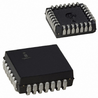
CS82C54
Description
IC TIMER PROG CMOS 8MHZ 28-PLCC
Manufacturer
Intersil
Type
Programmable Timerr
Specifications of CS82C54
Frequency
8MHz
Voltage - Supply
4.5 V ~ 5.5 V
Current - Supply
10mA
Operating Temperature
0°C ~ 70°C
Package / Case
28-PLCC
Peak Reflow Compatible (260 C)
No
Leaded Process Compatible
No
Mounting Type
Surface Mount
Rohs Compliant
No
Number Of Leads
28
Operating Frequency
8 MHz
Package Type
PLCC
Power, Standby
5 V
Technology
CMOS
Lead Free Status / RoHS Status
Contains lead / RoHS non-compliant
Count
-
Available stocks
Company
Part Number
Manufacturer
Quantity
Price
Company:

Part Number:
CS82C54
Manufacturer:
HAR/INT
Quantity:
5 380
Company:
Part Number:
CS82C54
Manufacturer:
HAR/INT
Quantity:
5 380
Part Number:
CS82C54
Manufacturer:
INTERSIL
Quantity:
20 000
Company:
Part Number:
CS82C54-10
Manufacturer:
HAR/INT
Quantity:
8 000
Company:
Part Number:
CS82C54-10
Manufacturer:
HAR/INT
Quantity:
8 000
Part Number:
CS82C54-10
Manufacturer:
INTERSIL
Quantity:
20 000


Since the Control Word Register and the three Counters have
separate addresses (selected by the A1, A0 inputs), and each
Control Word specifies the Counter it applies to (SC0, SC1
bits), no special instruction sequence is required. Any
programming sequence that follows the conventions above is
acceptable.
CONTROL WORD FORMAT
A1, A0 = 11; CS = 0; RD = 1; WR = 0
NOTE: Don’t Care bits (X) should be 0 to insure compatibility with
future products.
RW1 RW0
SC1
M2
D7
0
0
1
1
SC1
X
X
0
0
1
1
0
0
1
1
0
1
0
1
0
1
M1
SC0
0
0
1
1
0
0
Binary Counter 16-bit
Binary Coded Decimal (BCD) Counter (4 Decades)
D6
SC0
Counter Latch Command (See Read Operations)
Read/Write least significant byte only.
Read/Write most significant byte only.
Read/Write least significant byte first, then most
significant byte.
0
1
0
1
BCD - BINARY CODED DECIMAL
M0
0
1
0
1
0
1
RW1
D5
Select Counter 0
Select Counter 1
Select Counter 2
Read-Back Command (See Read Operations)
SC - SELECT COUNTER
Mode 0
Mode 1
Mode 2
Mode 3
Mode 4
Mode 5
RW - READ/WRITE
RW0
D4
M - MODE
8
M2
D3
M1
D2
M0
D1
BCD
D0
82C54
Control Word - Counter 0
LSB of Count - Counter 0
MSB of Count - Counter 0
Control Word - Counter 1
LSB of Count - Counter 1
MSB of Count - Counter 1
Control Word - Counter 2
LSB of Count - Counter 2
MSB of Count - Counter 2
Control Word - Counter 0
Control Word - Counter 1
Control Word - Counter 2
LSB of Count - Counter 2
LSB of Count - Counter 1
LSB of Count - Counter 0
MSB of Count - Counter 0
MSB of Count - Counter 1
MSB of Count - Counter 2
Control Word - Counter 2
Control Word - Counter 1
Control Word - Counter 0
LSB of Count - Counter 2
MSB of Count - Counter 2
LSB of Count - Counter 1
MSB of Count - Counter 1
LSB of Count - Counter 0
MSB of Count - Counter 0
POSSIBLE PROGRAMMING SEQUENCE
POSSIBLE PROGRAMMING SEQUENCE
POSSIBLE PROGRAMMING SEQUENCE
A1
A1
A1
1
0
0
1
0
0
1
1
1
1
1
1
1
0
0
0
0
1
1
1
1
1
1
0
0
0
0
A0
A0
A0
1
0
0
1
1
1
1
0
0
1
1
1
0
1
0
0
1
0
1
1
1
0
0
1
1
0
0
Related parts for CS82C54
Image
Part Number
Description
Manufacturer
Datasheet
Request
R

Part Number:
Description:
Standard Clock Oscillators 156.250MHz 2.5Volt 50ppm -10C +70C
Manufacturer:
TXC Corporation
Datasheet:
Part Number:
Description:
Standard Clock Oscillators 312.500MHz 3.3Volt 50ppm -10C +70C
Manufacturer:
TXC Corporation
Datasheet:
Part Number:
Description:
Standard Clock Oscillators 425.000MHz 2.5Volt 50ppm -10C +70C
Manufacturer:
TXC Corporation
Datasheet:
Part Number:
Description:
Standard Clock Oscillators 78.125MHz 2.5Volt 50ppm -10C +70C
Manufacturer:
TXC Corporation
Datasheet:
Part Number:
Description:
Standard Clock Oscillators 156.250MHz 3.3Volt 50ppm -10C +70C
Manufacturer:
TXC Corporation
Datasheet:
Part Number:
Description:
Standard Clock Oscillators 156.250MHz 2.5Volt 100ppm -10C +70C
Manufacturer:
TXC Corporation
Datasheet:
Part Number:
Description:
Standard Clock Oscillators 312.500MHz 3.3Volt 100ppm -10C +70C
Manufacturer:
TXC Corporation
Datasheet:
Part Number:
Description:
Standard Clock Oscillators 212.500MHz 3.3Volt 100ppm -10C +70C
Manufacturer:
TXC Corporation
Datasheet:
Part Number:
Description:
Standard Clock Oscillators 312.500MHz 2.5Volt 100ppm -10C +70C
Manufacturer:
TXC Corporation
Datasheet:
Part Number:
Description:
Standard Clock Oscillators 425.000MHz 2.5Volt 100ppm -10C +70C
Manufacturer:
TXC Corporation
Datasheet:
Part Number:
Description:
Standard Clock Oscillators 106.250MHz 3.3Volt 50ppm -10C +70C
Manufacturer:
TXC Corporation
Datasheet:
Part Number:
Description:
Standard Clock Oscillators 78.125MHz 2.5Volt 100ppm -10C +70C
Manufacturer:
TXC Corporation
Datasheet:
Part Number:
Description:
Standard Clock Oscillators 156.250MHz 3.3Volt 100ppm -10C +70C
Manufacturer:
TXC Corporation
Datasheet:
Part Number:
Description:
Standard Clock Oscillators 212.500MHz 2.5Volt 100ppm -10C +70C
Manufacturer:
TXC Corporation
Datasheet:
Part Number:
Description:
Standard Clock Oscillators 425.000MHz 3.3Volt 100ppm -10C +70C
Manufacturer:
TXC Corporation
Datasheet: