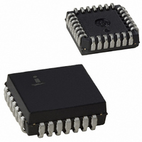
CS82C54 Intersil, CS82C54 Datasheet - Page 4

CS82C54
Manufacturer Part Number
CS82C54
Description
IC TIMER PROG CMOS 8MHZ 28-PLCC
Manufacturer
Intersil
Type
Programmable Timerr
Specifications of CS82C54
Frequency
8MHz
Voltage - Supply
4.5 V ~ 5.5 V
Current - Supply
10mA
Operating Temperature
0°C ~ 70°C
Package / Case
28-PLCC
Peak Reflow Compatible (260 C)
No
Leaded Process Compatible
No
Mounting Type
Surface Mount
Rohs Compliant
No
Number Of Leads
28
Operating Frequency
8 MHz
Package Type
PLCC
Power, Standby
5 V
Technology
CMOS
Lead Free Status / RoHS Status
Contains lead / RoHS non-compliant
Count
-
Available stocks
Company
Part Number
Manufacturer
Quantity
Price
Company:
Part Number:
CS82C54
Manufacturer:
HAR/INT
Quantity:
5 380
Company:
Part Number:
CS82C54
Manufacturer:
HAR/INT
Quantity:
5 380
Part Number:
CS82C54
Manufacturer:
INTERSIL
Quantity:
20 000
Company:
Part Number:
CS82C54-10
Manufacturer:
HAR/INT
Quantity:
8 000
Company:
Part Number:
CS82C54-10
Manufacturer:
HAR/INT
Quantity:
8 000
Part Number:
CS82C54-10
Manufacturer:
INTERSIL
Quantity:
20 000
AC Electrical Specifications
NOTE:
READ CYCLE
WRITE CYCLE
CLOCK AND GATE
1. Not tested, but characterized at initial design and at major process/design changes.
(10)
(11)
(12)
(13)
(14)
(15)
(16)
(17)
(18)
(19)
(20)
(21)
(22)
(23)
(24)
(25)
(26)
(27)
(28)
(29)
(30)
(1)
(2)
(3)
(4)
(5)
(6)
(7)
(8)
(9)
SYMBOL
TPWH
TPWL
TODG
TWW
TCLK
TGW
TWO
TWG
TAW
TSW
TWA
TDW
TWD
TWC
TRR
TRD
TGS
TGH
TOD
TAR
TSR
TRA
TAD
TDF
TRV
TRV
TGL
TCL
TR
TF
Address Stable Before RD
CS Stable Before RD
Address Hold Time After RD
RD Pulse Width
Data Delay from RD
Data Delay from Address
RD to Data Floating
Command Recovery Time
Address Stable Before WR
CS Stable Before WR
Address Hold Time After WR
WR Pulse Width
Data Setup Time Before WR
Data Hold Time After WR
Command Recovery Time
Clock Period
High Pulse Width
Low Pulse Width
Clock Rise Time
Clock Fall Time
Gate Width High
Gate Width Low
Gate Setup Time to CLK
Gate Hold Time After CLK
Output Delay from CLK
Output Delay from Gate
OUT Delay from Mode Write
CLK Delay for Loading
Gate Delay for Sampling
CLK Setup for Count Latch
PARAMETER
4
V
CC
= +5.0V ± 10%, Includes all Temperature Ranges
MIN
150
200
140
200
125
-40
30
95
25
60
60
50
50
50
50
-5
0
0
5
0
0
0
0
-
-
-
-
-
-
-
82C54
82C54
MAX
120
210
150
120
260
DC
85
25
25
55
40
40
-
-
-
-
-
-
-
-
-
-
-
-
-
-
-
-
-
-
MIN
165
165
100
-40
25
95
95
95
30
40
50
50
40
50
-5
0
0
5
0
0
0
0
0
-
-
-
-
-
-
-
82C54-10
MAX
240
185
100
100
DC
85
65
25
25
55
40
40
-
-
-
-
-
-
-
-
-
-
-
-
-
-
-
-
-
-
MIN
165
165
-40
25
95
95
95
80
30
30
50
50
40
50
-5
0
0
5
0
0
0
0
0
-
-
-
-
-
-
-
82C54-12
MAX
185
100
100
240
DC
85
65
25
25
55
40
40
-
-
-
-
-
-
-
-
-
-
-
-
-
-
-
-
-
-
UNITS
ns
ns
ns
ns
ns
ns
ns
ns
ns
ns
ns
ns
ns
ns
ns
ns
ns
ns
ns
ns
ns
ns
ns
ns
ns
ns
ns
ns
ns
ns
CONDITIONS
2, Note 1
TEST
1
1
1
1
1
1
1
1
1
1
1
1
1
1
1
1
1
1
1


