CS82C54 Intersil, CS82C54 Datasheet - Page 21
CS82C54
Manufacturer Part Number
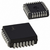
CS82C54
Description
IC TIMER PROG CMOS 8MHZ 28-PLCC
Manufacturer
Intersil
Type
Programmable Timerr
Specifications of CS82C54
Frequency
8MHz
Voltage - Supply
4.5 V ~ 5.5 V
Current - Supply
10mA
Operating Temperature
0°C ~ 70°C
Package / Case
28-PLCC
Peak Reflow Compatible (260 C)
No
Leaded Process Compatible
No
Mounting Type
Surface Mount
Rohs Compliant
No
Number Of Leads
28
Operating Frequency
8 MHz
Package Type
PLCC
Power, Standby
5 V
Technology
CMOS
Lead Free Status / RoHS Status
Contains lead / RoHS non-compliant
Count
-
Available stocks
Company
Part Number
Manufacturer
Quantity
Price
Company:

Part Number:
CS82C54
Manufacturer:
HAR/INT
Quantity:
5 380
Company:
Part Number:
CS82C54
Manufacturer:
HAR/INT
Quantity:
5 380
Part Number:
CS82C54
Manufacturer:
INTERSIL
Quantity:
20 000
Company:
Part Number:
CS82C54-10
Manufacturer:
HAR/INT
Quantity:
8 000
Company:
Part Number:
CS82C54-10
Manufacturer:
HAR/INT
Quantity:
8 000
Part Number:
CS82C54-10
Manufacturer:
INTERSIL
Quantity:
20 000


j
E1
x 45
Ceramic Leadless Chip Carrier Packages (CLCC)
B
h x 45
E2
o
-E-
e
-F-
1
A
o
L
0.010
S
L2
E H
S
0.007
D3
D
D1
B1
21
M
-H-
D2
B2
E F
e
S H S
A1
L3
E3
0.010
PLANE 2
PLANE 1
B3
L1
E
S
E F
S
82C54
J28.A
28 PAD CERAMIC LEADLESS CHIP CARRIER PACKAGE
NOTES:
SYMBOL
1. Metallized castellations shall be connected to plane 1 terminals
2. Unless otherwise specified, a minimum clearance of 0.015 inch
3. Symbol “N” is the maximum number of terminals. Symbols “ND”
4. The required plane 1 terminals and optional plane 2 terminals (if
5. The corner shape (square, notch, radius, etc.) may vary at the
6. Chip carriers shall be constructed of a minimum of two ceramic
7. Dimension “A” controls the overall package thickness. The maxi-
8. Dimensioning and tolerancing per ANSI Y14.5M-1982.
9. Controlling dimension: INCH.
ND
NE
A1
B1
B2
B3
D1
D2
D3
E1
E2
E3
and extend toward plane 2 across at least two layers of ceramic
or completely across all of the ceramic layers to make electrical
connection with the optional plane 2 terminals.
(0.38mm) shall be maintained between all metallized features
(e.g., lid, castellations, terminals, thermal pads, etc.)
and “NE” are the number of terminals along the sides of length
“D” and “E”, respectively.
used) shall be electrically connected.
manufacturer’s option, from that shown on the drawing.
layers.
mum “A” dimension is package height before being solder dipped.
e1
L1
L2
L3
A
B
D
E
N
e
h
L
j
MIL-STD-1835 CQCC1-N28 (C-4)
0.060
0.050
0.022
0.006
0.442
0.442
0.015
0.045
0.045
0.075
0.003
MIN
-
-
-
0.300 BSC
0.150 BSC
0.300 BSC
0.150 BSC
0.050 BSC
0.072 REF
0.040 REF
0.020 REF
INCHES
28
7
7
0.100
0.088
0.028
0.022
0.460
0.460
0.460
0.460
0.055
0.055
0.095
0.015
MAX
-
-
11.23
11.23
1.52
1.27
0.56
0.15
0.38
1.14
1.14
1.90
0.08
MIN
MILLIMETERS
-
-
-
1.83 REF
7.62 BSC
3.81 BSC
7.62 BSC
3.81 BSC
1.27 BSC
1.02 REF
0.51 REF
28
7
7
11.68
11.68
11.68
11.68
2.54
2.23
0.71
0.56
1.40
1.40
2.41
0.038
MAX
-
-
Rev. 0 5/18/94
NOTES
6, 7
2, 4
2
2
2
5
5
3
3
3
-
-
-
-
-
-
-
-
-
-
-
-
-
-
-
Related parts for CS82C54
Image
Part Number
Description
Manufacturer
Datasheet
Request
R

Part Number:
Description:
Standard Clock Oscillators 156.250MHz 2.5Volt 50ppm -10C +70C
Manufacturer:
TXC Corporation
Datasheet:
Part Number:
Description:
Standard Clock Oscillators 312.500MHz 3.3Volt 50ppm -10C +70C
Manufacturer:
TXC Corporation
Datasheet:
Part Number:
Description:
Standard Clock Oscillators 425.000MHz 2.5Volt 50ppm -10C +70C
Manufacturer:
TXC Corporation
Datasheet:
Part Number:
Description:
Standard Clock Oscillators 78.125MHz 2.5Volt 50ppm -10C +70C
Manufacturer:
TXC Corporation
Datasheet:
Part Number:
Description:
Standard Clock Oscillators 156.250MHz 3.3Volt 50ppm -10C +70C
Manufacturer:
TXC Corporation
Datasheet:
Part Number:
Description:
Standard Clock Oscillators 156.250MHz 2.5Volt 100ppm -10C +70C
Manufacturer:
TXC Corporation
Datasheet:
Part Number:
Description:
Standard Clock Oscillators 312.500MHz 3.3Volt 100ppm -10C +70C
Manufacturer:
TXC Corporation
Datasheet:
Part Number:
Description:
Standard Clock Oscillators 212.500MHz 3.3Volt 100ppm -10C +70C
Manufacturer:
TXC Corporation
Datasheet:
Part Number:
Description:
Standard Clock Oscillators 312.500MHz 2.5Volt 100ppm -10C +70C
Manufacturer:
TXC Corporation
Datasheet:
Part Number:
Description:
Standard Clock Oscillators 425.000MHz 2.5Volt 100ppm -10C +70C
Manufacturer:
TXC Corporation
Datasheet:
Part Number:
Description:
Standard Clock Oscillators 106.250MHz 3.3Volt 50ppm -10C +70C
Manufacturer:
TXC Corporation
Datasheet:
Part Number:
Description:
Standard Clock Oscillators 78.125MHz 2.5Volt 100ppm -10C +70C
Manufacturer:
TXC Corporation
Datasheet:
Part Number:
Description:
Standard Clock Oscillators 156.250MHz 3.3Volt 100ppm -10C +70C
Manufacturer:
TXC Corporation
Datasheet:
Part Number:
Description:
Standard Clock Oscillators 212.500MHz 2.5Volt 100ppm -10C +70C
Manufacturer:
TXC Corporation
Datasheet:
Part Number:
Description:
Standard Clock Oscillators 425.000MHz 3.3Volt 100ppm -10C +70C
Manufacturer:
TXC Corporation
Datasheet: