ISL90726UIE627Z-TK Intersil, ISL90726UIE627Z-TK Datasheet
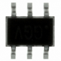
IC POT DGTL 50K OHM SC70-6

ISL90726UIE627Z-TK

Manufacturer Part Number
ISL90726UIE627Z-TK
Description
IC POT DGTL 50K OHM SC70-6
Manufacturer
Intersil
Series
XDCP™r
Datasheet

Specifications of ISL90726UIE627Z-TK

Taps
128
Resistance (ohms)
50K
Number Of Circuits
1
Temperature Coefficient
45 ppm/°C Typical
Memory Type
Volatile
Interface
I²C, 2-Wire Serial
Voltage - Supply
2.7 V ~ 5.5 V
Operating Temperature
-40°C ~ 85°C
Mounting Type
Surface Mount
Package / Case
SC-70-6, SC-88, SOT-363
Resistance In Ohms
50K
Lead Free Status / RoHS Status
Lead free / RoHS Compliant
Other names
ISL90726UIE627Z-TKTR

Available stocks

Company
Part Number
Manufacturer
Quantity
Price
Part Number:
ISL90726UIE627Z-TK
Manufacturer:
TI
Quantity:
150
Part Number:
ISL90726UIE627Z-TK
Manufacturer:
INTERSIL
Quantity:
11 163
Digitally Controlled Potentiometer (XDCP)
The Intersil ISL90726 is a digitally controlled potentiometer
(XDCP). The device consists of a resistor array, wiper
switches, and a control section. The wiper position is
controlled by an I
The potentiometer is implemented by a resistor array
composed of 127 resistive elements and a wiper switching
network. Between each element and at either end are tap
points accessible to the wiper terminal. The position of the
wiper element is controlled by the SDA and SCL inputs.
Pinout
Ordering Information
ISL90726WIE627Z-TK*
ISL90726UIE627Z-TK*
*Please refer to TB347 for details on reel specifications.
NOTE: These Intersil Pb-free plastic packaged products employ special Pb-free material sets, molding compounds/die attach materials, and 100%
matte tin plate plus anneal (e3 termination finish, which is RoHS compliant and compatible with both SnPb and Pb-free soldering operations).
Intersil Pb-free products are MSL classified at Pb-free peak reflow temperatures that meet or exceed the Pb-free requirements of IPC/JEDEC J
STD-020.
PART NUMBER
(Note)
GND
VDD
SCL
2
C interface.
1
2
3
(6 LD SC-70)
TOP VIEW
ANF
ANG
ISL90726
®
PART MARKING
1
Data Sheet
6
5
4
RL
RW
SDA
R
TOTAL
XDCP is a trademark of Intersil Americas Inc. Copyright Intersil Americas Inc. 2005, 2008. All Rights Reserved
1-888-INTERSIL or 1-888-468-3774
10
50
CAUTION: These devices are sensitive to electrostatic discharge; follow proper IC Handling Procedures.
(kΩ)
Features
• Volatile Solid-State Potentiometer
• I
• DCP Terminal Voltage, 2.7V to 5.5V
• Low Tempco
• 128 Wiper Tap Points
• Low Power CMOS
• Available R
• Power on Preset to Midscale
• Packaging
• Pb-Free (RoHS compliant)
Applications
• Mechanical Potentiometer Replacement
• Transducer Adjustment of Pressure, Temperature,
• Laser Diode and LED Biasing
• LCD Brightness and Contrast Adjustment
• Gain Control and Offset Adjustment
• DDR3 Margining
- Rheostat - 45 ppm/
- Divider - 15 ppm/
- Wiper Resistance 70Ω typ at V
- Active Current, 200µA Max
- Standby Current, 500nA Max
- 6 Ld SC-70
Position, Chemical, and Optical Sensors
TEMP RANGE
2
C Serial Bus Interface
-40 to +85
-40 to +85
August 26, 2008
(°C)
All other trademarks mentioned are the property of their respective owners.
|
Intersil (and design) is a registered trademark of Intersil Americas Inc.
TOTAL
Single Volatile 128-Tap XDCP™
Values = 50kΩ, 10kΩ
6 Ld SC-70
6 Ld SC-70
°C typical
°C typical
PACKAGE
(Pb-Free)
CC
= 3.3V
ISL90726
P6.049
P6.049
PKG. DWG. #
FN8244.4

Related parts for ISL90726UIE627Z-TK

ISL90726UIE627Z-TK Summary of contents

Page 1

... PART MARKING ISL90726WIE627Z-TK* ANF ISL90726UIE627Z-TK* ANG *Please refer to TB347 for details on reel specifications. NOTE: These Intersil Pb-free plastic packaged products employ special Pb-free material sets, molding compounds/die attach materials, and 100% matte tin plate plus anneal (e3 termination finish, which is RoHS compliant and compatible with both SnPb and Pb-free soldering operations). ...

Page 2

Pin Descriptions PIN NUMBER Block Diagram 2 ISL90726 SYMBOL VDD GND SCL SDA RW RL VDD SCL SDA INTERFACE WIPER REGISTER GND DESCRIPTION Supply Voltage Ground Open drain Serial Clock input ...

Page 3

... Ramp V Ramp Rate ISL90726 Thermal Information Thermal Resistance (Typical, Note SC- 0.3 CC Pb-Free Reflow Profile .see link below http://www.intersil.com/pbfree/Pb-FreeReflow.asp CC Recommended Operating Conditions Industrial . . . . . . . . . . . . . . . . . . . . . . . . . . . . . . . . . .-40°C to +85° 2.7V to 5.5V CC Power rating of each DCP . . . . . . . . . . . . . . . . . . . . . . . . . . . . .5mW TEST CONDITIONS W, U versions respectively V = 3.3V @ +25°C CC Voltage at pin from GND DCP register set between 20 hex and 7F hex ...

Page 4

Operating Specifications (Continued) SYMBOL PARAMETER t Power-up Delay D SERIAL INTERFACE SPECIFICATIONS V (Note 10) SDA, and SCL Input Buffer LOW IL Voltage V (Note 10) SDA, and SCL Input Buffer IH HIGH Voltage Hysteresis SDA and SCL Input Buffer ...

Page 5

Operating Specifications (Continued) SYMBOL PARAMETER Cb (Note 11) Capacitive Loading of SDA or SCL Rpu (Note 11) SDA and SCL Bus Pull-up Resistor Off-chip NOTES: 2. Typical values are for T = +25°C and 3.3V supply voltage LSB: ...

Page 6

I C Serial Interface The ISL90726 supports bidirectional bus oriented protocol. The protocol defines any device that sends data onto the bus as a transmitter and the receiving device as the receiver. The device controlling the transfer is a ...

Page 7

SCL FROM MASTER SDA OUTPUT FROM TRANSMITTER HIGH IMPEDANCE SDA OUTPUT FROM RECEIVER START FIGURE 2. ACKNOWLEDGE RESPONSE FROM RECEIVER S SIGNALS FROM T THE MASTER A IDENTIFICATION R T SIGNAL AT SDA 0 SIGNALS FROM THE ISL23711 FIGURE 3. ...

Page 8

... Accordingly, the reader is cautioned to verify that data sheets are current before placing orders. Information furnished by Intersil is believed to be accurate and reliable. However, no responsibility is assumed by Intersil or its subsidiaries for its use; nor for any infringements of patents or other rights of third parties which may result from its use ...

Related keywords