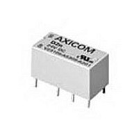
9-1393792-7 TE Connectivity, 9-1393792-7 Datasheet - Page 109

9-1393792-7
Manufacturer Part Number
9-1393792-7
Description
Electromechanical Relay DPDT 3A 12VDC 720Ohm Through Hole
Manufacturer
TE Connectivity
Type
Signal Relayr
Specifications of 9-1393792-7
Contact Arrangement
DPDT
Dc Coil Voltage
12 V
Coil Current
16.67 mA
Mounting
Through Hole
Relay Construction
Non-Latching
Coil Voltage Dc
12V
Contact Form
2 Form C
Voltage Rating (vdc)
220V
Voltage Rating (vac)
250V
Dropout Volt (min)
0.6VDCV
Coil Resistance
720Ohm
Pick-up Voltage (max)
8.4VDC
Maximum Power Rating
60W/125VA
Operate Time
5ms
Contact Current Rating
3A
Contact Material
AgNi/Au
Coil Suppression Diode
No
Push To Test Button
No
Led Indicator
No
Seal
Unsealed
Product Height (mm)
11mm
Product Depth (mm)
10mm
Product Length (mm)
20.2mm
Operating Temp Range
-25C to 85C
Pin Count
8
Mounting Style
Through Hole
Termination Style
PC Pin
Package / Case
DIP
Lead Free Status / Rohs Status
Compliant
- Current page: 109 of 484
- Download datasheet (15Mb)
Features
• Through hole type terminals.
• Meets Bellcore GR 1089, FCC Part 68 and ITU-T K20.
• For applications in telecommunications, office automation, consumer
• Immersion cleanable, plastic sealed case.
• 300mW coil.
• Ultrasonic cleaning not recommended.
Contact Data @ 23 C (except as noted)
Arrangement: 4 Form C (DPDT) bifurcatedcontacts.
Material: Stationary: Silver-nickel, gold covered.
Ratings: Max. Switched Current: 1.25A.
Initial Contact Resistance: <70 milliohms @ 10mA / 20mV.
Expected Mechanical Life: 100,000,000 ops.
Expected Electrical Life: 10 million operations @ 10mA / 30mVDC.
Thermoelectric potential: <10 V.
High Frequency Data
Capacitance: Between Open Contacts: 2pF, max.
RF Characteristics: Isolation at 100 / 900 MHz: -31.2 db / -17.2 db.
Initial Dielectric Strength
Between Open Contacts: 700Vrms for 1 minute.
Between Coil and Contacts: 1,800Vrms for 1 minute.
Between Poles: 700Vrms for 1 minute.
Surge Voltage Resistance per Bellcore TR-NWT-001089 (2 / 10 s),
FCC 68 (10 / 160 s) and IEC (10 / 700 s):
Initial Insulation Resistance
Between Contact and Coil: 10
Dimensions are shown for
reference purposes only.
electronics, medical equipment, measurement and control equipment.
Between Open Contacts: 1,500V.
Between Coil and Contacts: 2,500V.
Between Poles: 1,500V.
Max. Carry Current: 1.25A (at max ambient temperature.
Max. Switched Voltage: 150VDC, 150VAC.
Max. Switched Power: 30W DC or 62.5VA AC.
UL/CSA Ratings: 400mA @ 125VAC; 1.25A @ 24VDC.
Between Coil and Contacts: 4pF, max.
Between Poles: 2pF, max.
Insertion loss at 100 / 900 MHz: -0.05 db / -0.91 db.
V. S. W. R. at 100 / 900 MHz: 1.03 db / 1.31 db.
5 million operations @ cable load open end.
200,000 operations @ 1.25A / 24VDC, res.
200,000 operations @ 200mA / 150VDC, res.
9
ohms or more @ 500VDC.
Dimensions are in inches over
(millimeters) unless otherwise
specified.
Catalog 1308242
Issued 3-03
Mechanical Data
Termination: DIP compatible, printed circuit terminals.
Mounting Position: Any.
Enclosure Type: Immersion cleanable (IP67) plastic case.
Weight: 0.25 oz. (7g) approximately.
MT4
4PDT Telecom/Signal PC Board Relays
Users should thoroughly review the technical data before selecting a product part
number. It is recommended that users also seek out the pertinent approvals files of
the agencies/laboratories and review them to ensure the product meets the
requirements for a given application.
Coil Data @ 23 C
Voltage: 4.5 to 48VDC.
Nominal Power: See Coil Data table.
Duty Cycle: Continuous.
Operate Data @ 23 C
Operate and Release Voltage: See values in chart above.
Operate Time (at nominal voltage): 4 ms, typ.; 6 ms, max.
Release Time (without diode in parallel): 1 ms, typ.; 3 ms, max.
Release Time (with diode in parallel): 4 ms, typ.; 6 ms, max.
Bounce Time (at contact close): 1 ms, typ.; 5 ms, max.
Maximum Switching Rate (no load): 50 operations/s.
Environmental Data
Temperature Range: -55 C to +85 C.
Maximum Allowable Coil Temperature: 100 C.
Thermal Resistance: < 105K/W.
Shock, half sinus, 11 ms: Functional: 10g.
Vibration, 10-500 Hz.: Functional: 10g.
Needle Flame Test: Application Time 10s.
Resistance to Soldering: 260 C for 10s.
Coil Data @ 23 C
Nominal
Voltage
(VDC)
300mW versions
12
24
48
File E111441
File 176679-1079886
16501-001
4.5
5
9
Specifications and availability
subject to change.
series
Minimum
Voltage
(VDC)
17.1
34.1
3.2
3.6
6.4
8.6
Maximum
Voltage
Destructive: 100g.
(VDC)
15.6
20.8
41.6
83.2
7.8
8.65
Minimum
Release
Voltage
(VDC)
0.45
0.5
0.9
1.2
2.4
4.8
Resistance
(Ohms)
1,920
7,680
10%
270
480
www.tycoelectronics.com
Technical support:
Refer to inside back cover.
67
83
AXICOM
Number
C 93807
C 93801
C 93805
C 93802
C 93803
C 93804
Part
337
Related parts for 9-1393792-7
Image
Part Number
Description
Manufacturer
Datasheet
Request
R

Part Number:
Description:
CRIMP, RECEPTACLE
Manufacturer:
TE Connectivity
Datasheet:

Part Number:
Description:
PIGGYBACK DISCONNECT, 6.35MM, CRIMP BLUE
Manufacturer:
TE Connectivity
Datasheet:

Part Number:
Description:
Manufacturer:
TE Connectivity
Datasheet:

Part Number:
Description:
CRIMP TERMINAL, FEMALE, BLUE
Manufacturer:
TE Connectivity
Datasheet:

Part Number:
Description:
Manufacturer:
TE Connectivity
Datasheet:

Part Number:
Description:
CONN HEADR BRKWAY .100 13POS R/A
Manufacturer:
Tyco Electronics
Datasheet:

Part Number:
Description:
CONN HEADR BRKWAY .100 13POS R/A
Manufacturer:
Tyco Electronics
Datasheet:

Part Number:
Description:
CONN HDR BRKWAY .100 13POS VERT
Manufacturer:
Tyco Electronics
Datasheet:

Part Number:
Description:
CONN HDR BRKWAY .100 13POS VERT
Manufacturer:
Tyco Electronics
Datasheet:

Part Number:
Description:
CONN HDR BRKWAY .100 13POS VERT
Manufacturer:
Tyco Electronics
Datasheet:

Part Number:
Description:
CONN HEADR BRKWAY .100 13POS R/A
Manufacturer:
Tyco Electronics
Datasheet:

Part Number:
Description:
CONN HEADR BRKWAY .100 13POS STR
Manufacturer:
Tyco Electronics
Datasheet:

Part Number:
Description:
CONN HEADR BRKWAY .100 13POS STR
Manufacturer:
Tyco Electronics
Datasheet:

Part Number:
Description:
CONN HEADR BRKWAY .100 13POS STR
Manufacturer:
Tyco Electronics
Datasheet:

Part Number:
Description:
CONN HEADR BRKWAY .100 13POS R/A
Manufacturer:
Tyco Electronics
Datasheet:


