9-1393792-7 TE Connectivity, 9-1393792-7 Datasheet - Page 440
9-1393792-7
Manufacturer Part Number
9-1393792-7
Description
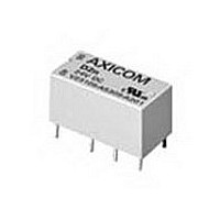
Electromechanical Relay DPDT 3A 12VDC 720Ohm Through Hole
Manufacturer
TE Connectivity
Type
Signal Relayr
Specifications of 9-1393792-7
Contact Arrangement
DPDT
Dc Coil Voltage
12 V
Coil Current
16.67 mA
Mounting
Through Hole
Relay Construction
Non-Latching
Coil Voltage Dc
12V
Contact Form
2 Form C
Voltage Rating (vdc)
220V
Voltage Rating (vac)
250V
Dropout Volt (min)
0.6VDCV
Coil Resistance
720Ohm
Pick-up Voltage (max)
8.4VDC
Maximum Power Rating
60W/125VA
Operate Time
5ms
Contact Current Rating
3A
Contact Material
AgNi/Au
Coil Suppression Diode
No
Push To Test Button
No
Led Indicator
No
Seal
Unsealed
Product Height (mm)
11mm
Product Depth (mm)
10mm
Product Length (mm)
20.2mm
Operating Temp Range
-25C to 85C
Pin Count
8
Mounting Style
Through Hole
Termination Style
PC Pin
Package / Case
DIP
Lead Free Status / Rohs Status
Compliant


1240
Timing Mode
Timing Specifications
Timing Ranges: 1 to 1,000 sec.
Timing Adjustment: Time delay is set by connecting an appropriately rated
Accuracy: Repeat Accuracy:
Reset Time: 100 ms, max., in the timing or time-out condition.
Output Switch Data
Arrangement: 1 Form A (SPST-NO).
Rating: 5A, inductive, at nominal operating voltage.
Inrush: Not to exceed 10A for one cycle.
Max. Leakage Current: 4mA rms.
Expected Electrical Life: 10,000,000 operations at rated load.
Initial Dielectric Strength
Between Active Terminals and Outside of Case: 1,480VAC for one min.
Outline Dimensions
On-Delay – VTM-1 in-line timing module is wired in series with the load
circuit. Time delay is initiated when power is applied to the series network.
Connecting a resistor across the center terminals provides tamper-proof
setting of time delay from 1-1000 sec.
Dimensions are shown for
reference purposes only.
resistor or potentiometer between the center two
terminals. As supplied, the unit provides a nominal 1
second delay. Add 10k ohm of resistance for every
additional second of delay required. For example: 5
seconds = 40k ohms; 10 seconds = 90k ohms.
2%
Dimensions are in inches over
(millimeters) unless otherwise
specified.
Catalog 1308242
Issued 3-03
VTM-1
Specification Grade, On-Delay
Timing Module
• On-delay timing mode
• Timing from 1 to 1000 sec.
• 1A solid state SPST-NO output
• 0.25" (6.35) quick connect terminals
• Universal voltage: 24 to 240VAC/VDC
• Rated to 10 million operations
Users should thoroughly review the technical data before selecting a product part
number. It is recommended that user also seek out the pertinent approvals files of
the agencies/laboratories and review them to ensure the product meets the
requirements for a given application.
Input Data @ 25 C
Operating Voltage: Universal: 24-240VAC/VDC (19-288VAC/VDC).
Current: 2mA (max.) required to operate timer regardless of output state.
Power Requirement: 3W, max.
Transient Protection: MOV across input 2,000V for 11 s on line side of
load.
Environmental Data
Temperature Range: Storage: -40 C to +85 C.
Mechanical Data
Mounting:
Termination: 0.250 in (6.35) quick connect terminals for input line, load
Weight: 3 oz. (84g) approximately.
Ordering Information
Authorized distributors are likely to stock the following:
VTM-1
Wiring Diagram
Notes:
1. Do not operate timer
2. For a time delay of 1
Part Number
without connecting load
in series with line voltage.
second, connect a jumper
across the center two
terminals.
VTM-1
File E60363
File LR51332
Specifications and availability
subject to change.
Screw mount in horizontal or vertical position through built-in
mounting ears.
output and timing resistor connection.
On-Delay
series
Mode
Operating: -30 C to +65 C.
24-240VAC or VDC
Input Voltage
www.tycoelectronics.com
Technical support:
Refer to inside back cover.
AGASTAT
Related parts for 9-1393792-7
Image
Part Number
Description
Manufacturer
Datasheet
Request
R

Part Number:
Description:
CRIMP, RECEPTACLE
Manufacturer:
TE Connectivity
Datasheet:

Part Number:
Description:
PIGGYBACK DISCONNECT, 6.35MM, CRIMP BLUE
Manufacturer:
TE Connectivity
Datasheet:

Part Number:
Description:
Manufacturer:
TE Connectivity
Datasheet:

Part Number:
Description:
CRIMP TERMINAL, FEMALE, BLUE
Manufacturer:
TE Connectivity
Datasheet:
Part Number:
Description:
Manufacturer:
TE Connectivity
Datasheet:

Part Number:
Description:
CONN HEADR BRKWAY .100 13POS R/A
Manufacturer:
Tyco Electronics
Datasheet:
Part Number:
Description:
CONN HEADR BRKWAY .100 13POS R/A
Manufacturer:
Tyco Electronics
Datasheet:
Part Number:
Description:
CONN HDR BRKWAY .100 13POS VERT
Manufacturer:
Tyco Electronics
Datasheet:
Part Number:
Description:
CONN HDR BRKWAY .100 13POS VERT
Manufacturer:
Tyco Electronics
Datasheet:
Part Number:
Description:
CONN HDR BRKWAY .100 13POS VERT
Manufacturer:
Tyco Electronics
Datasheet:
Part Number:
Description:
CONN HEADR BRKWAY .100 13POS R/A
Manufacturer:
Tyco Electronics
Datasheet:
Part Number:
Description:
CONN HEADR BRKWAY .100 13POS STR
Manufacturer:
Tyco Electronics
Datasheet:
Part Number:
Description:
CONN HEADR BRKWAY .100 13POS STR
Manufacturer:
Tyco Electronics
Datasheet:
Part Number:
Description:
CONN HEADR BRKWAY .100 13POS STR
Manufacturer:
Tyco Electronics
Datasheet:
Part Number:
Description:
CONN HEADR BRKWAY .100 13POS R/A
Manufacturer:
Tyco Electronics
Datasheet: