9-1393792-7 TE Connectivity, 9-1393792-7 Datasheet - Page 445
9-1393792-7
Manufacturer Part Number
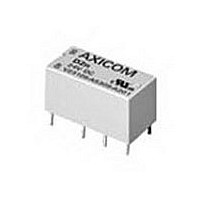
9-1393792-7
Description
Electromechanical Relay DPDT 3A 12VDC 720Ohm Through Hole
Manufacturer
TE Connectivity
Type
Signal Relayr
Specifications of 9-1393792-7
Contact Arrangement
DPDT
Dc Coil Voltage
12 V
Coil Current
16.67 mA
Mounting
Through Hole
Relay Construction
Non-Latching
Coil Voltage Dc
12V
Contact Form
2 Form C
Voltage Rating (vdc)
220V
Voltage Rating (vac)
250V
Dropout Volt (min)
0.6VDCV
Coil Resistance
720Ohm
Pick-up Voltage (max)
8.4VDC
Maximum Power Rating
60W/125VA
Operate Time
5ms
Contact Current Rating
3A
Contact Material
AgNi/Au
Coil Suppression Diode
No
Push To Test Button
No
Led Indicator
No
Seal
Unsealed
Product Height (mm)
11mm
Product Depth (mm)
10mm
Product Length (mm)
20.2mm
Operating Temp Range
-25C to 85C
Pin Count
8
Mounting Style
Through Hole
Termination Style
PC Pin
Package / Case
DIP
Lead Free Status / Rohs Status
Compliant


Dimensions are shown for
reference purposes only.
Timing Mode
Timing Specifications
Timing Ranges: 0.5 to 10 / 3 to 60 sec.; 3 to 60 min.
Timing Adjustment: External resistor or potentiometer. An external
Accuracy: Repeat Accuracy:
Reset Time: 50 ms, max.
Output Switch Data
Arrangement: Solid state 1 Form A (SPST-NO).
Rating: 1A, inductive, at nominal operating voltage.
Expected Electrical Life: 100,000,000 operations at rated load.
Initial Dielectric Strength
Between Terminals and Mounting: 3,000VAC rms.
Between Input and Output: 1,500VAC rms.
Outline Dimensions
Wiring Diagram
Interval.
VOLTAGE
POLARITY SHOWN
FOR DC
MODELS
INPUT
LOAD
(50.8)
Overall Accuracy: 2% at R = 1 megohm.
2.00
ACCEPTS #8 SCREW
1
2
3
.170 DIA (4.32)
resistance of 1 megohm is required to obtain the
maximum time for all ranges. To determine the actual
resistance needed to obtain the required time delay,
use the following formula:
R
t
(50.8)
2.00
=
(
5
4
T
T
req
max
- T
- T
1%
R
min
t
min
.250 (6.35) X .032 (.813)
)
An external resistance of 1 megohm is
required to obtain the maximum time
for all ranges. To determine the actual
resistance needed to obtain the
required time delay, use the following
formula:
R
QUICK CONNECTS
(31.8)
t
Dimensions are in inches over
(millimeters) unless otherwise
specified.
x 1,000,000 ohms
1.25
=
(
T
T
req
max
- T
- T
(22.5)
.885
min
min
)
x 1,000,000 ohms
Catalog 1308242
Issued 3-03
VTM3
Interval
Timing Module
• Interval timing mode
• Reliable solid state timing circuitry.
• Excellent transient protection.
• Compact design.
• Flame retardant, solvent resistant housing.
Users should thoroughly review the technical data before selecting a product part
number. It is recommended that user also seek out the pertinent approvals files of
the agencies/laboratories and review them to ensure the product meets the
requirements for a given application.
Input Data @ 25 C
Voltage:( 10%): 12 VAC/VDC, 24VAC/VDC, 120 VAC/VDC.
Power Requirement: 4W, with rated load.
Transient Protection: Non-repetitive transients of the following magni-
tudes will not cause spurious operation of affect function and accuracy.
Current Drain: Less than 5mA.
Environmental Data
Temperature Range: Storage: -40 C to +85 C.
Mechanical Data
Mounting: Panel mount with one #8 screw.
Termination: 0.250 in (6.35) quick connect terminals.
Weight: 4 oz. (112g) approximately.
Ordering Information
Authorized distributors are likely to stock the following:
None at present.
Interval
Timing Module
Series VTM3
File E60363
File LR33434
VTM3
Specifications and availability
subject to change.
|
* Min. source impedance of 100 ohms.
Operating Voltage
12, 24 VAC/VDC
120 VAC/VDC
series
Operating: -40 C to +65 C.
Input Voltage
A = 120VAC/VDC
E = 24VAC/VDC
Q = 12VAC/VDC
A
|
<0.1 ms
2,580V
860V*
2,150V*
<1 ms
208V*
Time Range
CD = 0.5 - 10 sec.
DD = 3 - 60 sec.
GD = 3 - 60 min.
www.tycoelectronics.com
Technical support:
Refer to inside back cover.
CD
|
AGASTAT
1245
Related parts for 9-1393792-7
Image
Part Number
Description
Manufacturer
Datasheet
Request
R

Part Number:
Description:
CRIMP, RECEPTACLE
Manufacturer:
TE Connectivity
Datasheet:

Part Number:
Description:
PIGGYBACK DISCONNECT, 6.35MM, CRIMP BLUE
Manufacturer:
TE Connectivity
Datasheet:

Part Number:
Description:
Manufacturer:
TE Connectivity
Datasheet:

Part Number:
Description:
CRIMP TERMINAL, FEMALE, BLUE
Manufacturer:
TE Connectivity
Datasheet:
Part Number:
Description:
Manufacturer:
TE Connectivity
Datasheet:

Part Number:
Description:
CONN HEADR BRKWAY .100 13POS R/A
Manufacturer:
Tyco Electronics
Datasheet:
Part Number:
Description:
CONN HEADR BRKWAY .100 13POS R/A
Manufacturer:
Tyco Electronics
Datasheet:
Part Number:
Description:
CONN HDR BRKWAY .100 13POS VERT
Manufacturer:
Tyco Electronics
Datasheet:
Part Number:
Description:
CONN HDR BRKWAY .100 13POS VERT
Manufacturer:
Tyco Electronics
Datasheet:
Part Number:
Description:
CONN HDR BRKWAY .100 13POS VERT
Manufacturer:
Tyco Electronics
Datasheet:
Part Number:
Description:
CONN HEADR BRKWAY .100 13POS R/A
Manufacturer:
Tyco Electronics
Datasheet:
Part Number:
Description:
CONN HEADR BRKWAY .100 13POS STR
Manufacturer:
Tyco Electronics
Datasheet:
Part Number:
Description:
CONN HEADR BRKWAY .100 13POS STR
Manufacturer:
Tyco Electronics
Datasheet:
Part Number:
Description:
CONN HEADR BRKWAY .100 13POS STR
Manufacturer:
Tyco Electronics
Datasheet:
Part Number:
Description:
CONN HEADR BRKWAY .100 13POS R/A
Manufacturer:
Tyco Electronics
Datasheet: