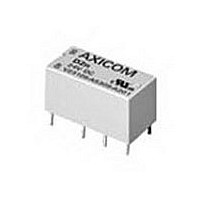
9-1393792-7 TE Connectivity, 9-1393792-7 Datasheet - Page 87

9-1393792-7
Manufacturer Part Number
9-1393792-7
Description
Electromechanical Relay DPDT 3A 12VDC 720Ohm Through Hole
Manufacturer
TE Connectivity
Type
Signal Relayr
Specifications of 9-1393792-7
Contact Arrangement
DPDT
Dc Coil Voltage
12 V
Coil Current
16.67 mA
Mounting
Through Hole
Relay Construction
Non-Latching
Coil Voltage Dc
12V
Contact Form
2 Form C
Voltage Rating (vdc)
220V
Voltage Rating (vac)
250V
Dropout Volt (min)
0.6VDCV
Coil Resistance
720Ohm
Pick-up Voltage (max)
8.4VDC
Maximum Power Rating
60W/125VA
Operate Time
5ms
Contact Current Rating
3A
Contact Material
AgNi/Au
Coil Suppression Diode
No
Push To Test Button
No
Led Indicator
No
Seal
Unsealed
Product Height (mm)
11mm
Product Depth (mm)
10mm
Product Length (mm)
20.2mm
Operating Temp Range
-25C to 85C
Pin Count
8
Mounting Style
Through Hole
Termination Style
PC Pin
Package / Case
DIP
Lead Free Status / Rohs Status
Compliant
- Current page: 87 of 484
- Download datasheet (15Mb)
.0315 DIA.
PC Board Layouts (Bottom Views)
Through-Hole
Dimensions are shown for
reference purposes only.
Ordering Information
Our authorized distributors are more likely to stock the following items for immediate delivery.
V23026A1001B201
V23026A1002B201
V23026A1004B201
Outline Dimensions
Through-Hole
Surface Mount
INDEX
MARK
1. Basic Series:
2. Termination:
3. Function Type:
4. Coil Voltage:
5. Contact Type:
*Consult factory for tape and reel packaging.
(.8
Consult factory regarding availability of models meeting FCC Part 68/1500V surge requirement.
V23026 = P1 Miniature, printed circuit board relay.
00 = Single Coil Non-Latching, Through-Hole terminals
05 = Single Coil Latching
7 = 1.5VDC
(1) For single coil latching versions only (C1, F1), 5 =1.5VDC and 7 = 9VDC
B201 = Bifurcated, 1 Form C (SPDT).
Through-Hole
Surface Mount
.05)
.016 Ø
(.4)
.0 02
.512 MAX.
.531 MAX.
(13)
(13.5)
(1)
.100 TYP .
(2.54)
.008 Ø
6 = 3VDC
Non-Latching
(.2)
V23026D1021B201
V23026D1022B201
V23026D1024B201
.047
(1.2)
A1
D1
.138 MAX.
.272 MAX.
.315 MAX.
(3.5)
(.15)
.06
(6.9)
.012 MAX.
(8)
1 = 5VDC
(.3)
(1.26)
.05
Dual Coil Latching
.100 TYP .
.08 MAX.
Dimensions are in inches over
(millimeters) unless otherwise
specified.
.30 MAX.
(2.54)
(7 .62)
(2)
B1
E1
Typical Part Number
5 = 9VDC
.31 MAX.
.41 MAX.
(10.3)
(7 .9)
(1)
Single Coil Latching
2 = 12VDC
(0.5)
.02
02 = Single Coil Non-Latching, Surface-Mount terminals
10 = Dual Coil Latching
0 /8
C1
F1
Catalog 1308242
(2) 24V coil not available on dual coil version
B V23026
Issued 3-03
3 = 15VDC
Surface Mount
INDEX
MARK
Wiring Diagrams (Bottom Views)
INDEX
MARK
For non-latching versions, coil polarity must be observed.
For single coil latching versions, polarity shown results in "set" condition.
Reverse polarity results in "reset" condition.
Diagram indicates de-energized position for non-latching and "reset" position
for single coil latching.
Dual Coil Latching
INDEX
MARK
Single Coil Non-Latching & Single Coil Latching
Diagram indicates relay in the "reset" position, with "reset" coil most recently
energized as shown. Energizing "set" coil as shown will transfer the contacts.
(3.4)
.134
4 = 24VDC
Specifications and availability
subject to change.
1
10
1
10
(2)
A1
.047
(1.2)
3
+
3
+
8
8
-
-
SET
RESET
00
5
+
5
6
.067
(1.7)
(2.54)
.100
(7 .62)
.004
(.10)
.3
2
www.tycoelectronics.com
Technical support:
Refer to inside back cover.
B201
AXICOM
315
Related parts for 9-1393792-7
Image
Part Number
Description
Manufacturer
Datasheet
Request
R

Part Number:
Description:
CRIMP, RECEPTACLE
Manufacturer:
TE Connectivity
Datasheet:

Part Number:
Description:
PIGGYBACK DISCONNECT, 6.35MM, CRIMP BLUE
Manufacturer:
TE Connectivity
Datasheet:

Part Number:
Description:
Manufacturer:
TE Connectivity
Datasheet:

Part Number:
Description:
CRIMP TERMINAL, FEMALE, BLUE
Manufacturer:
TE Connectivity
Datasheet:

Part Number:
Description:
Manufacturer:
TE Connectivity
Datasheet:

Part Number:
Description:
CONN HEADR BRKWAY .100 13POS R/A
Manufacturer:
Tyco Electronics
Datasheet:

Part Number:
Description:
CONN HEADR BRKWAY .100 13POS R/A
Manufacturer:
Tyco Electronics
Datasheet:

Part Number:
Description:
CONN HDR BRKWAY .100 13POS VERT
Manufacturer:
Tyco Electronics
Datasheet:

Part Number:
Description:
CONN HDR BRKWAY .100 13POS VERT
Manufacturer:
Tyco Electronics
Datasheet:

Part Number:
Description:
CONN HDR BRKWAY .100 13POS VERT
Manufacturer:
Tyco Electronics
Datasheet:

Part Number:
Description:
CONN HEADR BRKWAY .100 13POS R/A
Manufacturer:
Tyco Electronics
Datasheet:

Part Number:
Description:
CONN HEADR BRKWAY .100 13POS STR
Manufacturer:
Tyco Electronics
Datasheet:

Part Number:
Description:
CONN HEADR BRKWAY .100 13POS STR
Manufacturer:
Tyco Electronics
Datasheet:

Part Number:
Description:
CONN HEADR BRKWAY .100 13POS STR
Manufacturer:
Tyco Electronics
Datasheet:

Part Number:
Description:
CONN HEADR BRKWAY .100 13POS R/A
Manufacturer:
Tyco Electronics
Datasheet:


