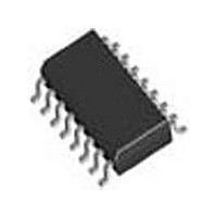
SI3018-F-FSR Silicon Laboratories Inc, SI3018-F-FSR Datasheet - Page 91

SI3018-F-FSR
Manufacturer Part Number
SI3018-F-FSR
Description
Modem Chip Chipset 16-Pin SOIC T/R
Manufacturer
Silicon Laboratories Inc
Datasheet
1.SI3018-F-FSR.pdf
(112 pages)
Specifications of SI3018-F-FSR
Package
16SOIC
Main Category
Chipset
Sub-category
Data/Voice
Typical Operating Supply Voltage
3.3 V
Power Supply Type
Digital
Typical Supply Current
8.5 mA
Minimum Operating Supply Voltage
3 V
Maximum Operating Supply Voltage
3.6 V
Data Rate
54.6875Kbps
Operating Supply Voltage (typ)
3.3V
Operating Supply Voltage (min)
3V
Operating Supply Voltage (max)
3.6V
Operating Temp Range
0C to 70C
Operating Temperature Classification
Commercial
Pin Count
16
Mounting
Surface Mount
Lead Free Status / Rohs Status
Compliant
Available stocks
Company
Part Number
Manufacturer
Quantity
Price
Company:
Part Number:
SI3018-F-FSR
Manufacturer:
SiliconL
Quantity:
52 026
Company:
Part Number:
SI3018-F-FSR
Manufacturer:
SILICON
Quantity:
57
Part Number:
SI3018-F-FSR
Manufacturer:
SILICONLABS/芯科
Quantity:
20 000
Register 43. Line Current/Voltage Threshold Interrupt (Si3019 line-side only)
Reset settings = 0000_0000
Register 44. Line Current/Voltage Threshold Interrupt Control (Si3019 line-side only)
Reset settings = 0000_0000
Bit
7:0
Bit
7:4
3
2
1
0
Name
Name
Type
Type
Bit
Bit
Reserved Read returns zero.
CVT[7:0]
Name
Name
CVM
CVS
CVP
CVI
D7
D7
Current/Voltage Threshold.
These bits determine the threshold at which an interrupt is generated from either the LCS or
LVS register. This interrupt can be generated to occur when the line current or line voltage
rises above or drops below the value in the CVT[7:0] register.
Current/Voltage Interrupt.
0 = The current/voltage threshold has not been crossed.
1 = The current/voltage threshold is crossed. If the CVM and INTE bits are set, a hardware
interrupt occurs on the AOUT/INT pin. Once set, this bit must be written to 0 to be cleared.
Current/Voltage Select.
0 = The line current shown in the LCS2 register is used to generate an interrupt.
1 = The line voltage shown in the LVS register is used to generate an interrupt.
Current/Voltage Interrupt Mask.
0 = The current/voltage threshold being triggered does not cause a hardware interrupt on the
AOUT/INT pin.
1 = The current/voltage threshold being triggered causes a hardware interrupt on the
AOUT/INT pin.
Current/Voltage Interrupt Polarity.
0 = The current/voltage threshold is triggered by the absolute value of the number in either
the LCS2 or LVS register falling below the value in the CVT[7:0] register.
1 = The current/voltage threshold is triggered by the absolute value of the number in either
the LCS2 or LVS register rising above the value in the CVT[7:0] register.
D6
D6
D5
D5
Rev. 1.31
D4
D4
CVT[7:0]
R/W
Function
Function
R/W
CVI
D3
D3
Si3050 + Si3018/19
CVS
R/W
D2
D2
CVM
R/W
D1
D1
CVP
R/W
D0
D0
91


