ADSP-21371KSWZ-2B Analog Devices Inc, ADSP-21371KSWZ-2B Datasheet - Page 18
ADSP-21371KSWZ-2B
Manufacturer Part Number
ADSP-21371KSWZ-2B
Description
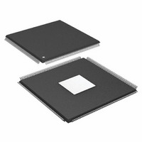
IC DSP 32BIT 266MHZ 208-LQFP
Manufacturer
Analog Devices Inc
Series
SHARC®r
Type
Floating Pointr
Specifications of ADSP-21371KSWZ-2B
Package / Case
208-LQFP
Interface
DAI, DPI
Operating Temperature
0°C ~ 70°C
Clock Rate
266MHz
Non-volatile Memory
ROM (512 kB)
On-chip Ram
128kB
Voltage - I/o
3.30V
Voltage - Core
1.20V
Mounting Type
Surface Mount
Svhc
No SVHC (18-Jun-2010)
Base Number
21371
Core Frequency Typ
266MHz
Dsp Type
Floating Point
Mmac
532
No. Of Pins
208
Interface Type
SPI, UART
Rohs Compliant
Yes
Operating Temperature Range
0°C To +70°C
Lead Free Status / RoHS Status
Lead free / RoHS Compliant
Available stocks
Company
Part Number
Manufacturer
Quantity
Price
Company:

Part Number:
ADSP-21371KSWZ-2B
Manufacturer:
Analog Devices Inc
Quantity:
10 000
Part Number:
ADSP-21371KSWZ-2B
Manufacturer:
ADI/亚德诺
Quantity:
20 000


ADSP-21371
Note the definitions of various clock periods shown in
which are a function of CLKIN and the appropriate ratio con
trol shown in
Table 11. ADSP-21371 CLKOUT and CCLK Clock
Generation Operation
Table 12. Clock Periods
1
Use the exact timing information given. Do not attempt to
derive parameters from the addition or subtraction of others.
While addition or subtraction would yield meaningful results
for an individual device, the values given in this data sheet
reflect statistical variations and worst cases. Consequently, it is
not meaningful to add parameters to derive longer times. See
Figure 36 on Page 44
ence levels.
Switching Characteristics specify how the processor changes its
signals. Circuitry external to the processor must be designed for
compatibility with these signal characteristics. Switching char
acteristics describe what the processor will do in a given
circumstance. Use switching characteristics to ensure that any
timing requirement of a device connected to the processor (such
as memory) is satisfied.
Timing Requirements apply to signals that are controlled by cir
cuitry external to the processor, such as the data input for a read
operation. Timing requirements guarantee that the processor
operates correctly with other devices.
Timing
Requirements
CLKIN
CCLK
Timing
Requirements
t
t
t
t
t
t
where:
SR = serial port-to-core clock ratio (wide range, determined by SPORT CLKDIV
CK
CCLK
PCLK
SCLK
SDCLK
SPICLK
bits in DIVx register)
SPIR = SPI-to-Core Clock Ratio (wide range, determined by SPIBAUD register
setting)
SDR=SDRAM-to-Core Clock Ratio (Values determined by bits 20-18 of the
PMCTL register)
Table
11.
under Test Conditions for voltage refer
Description
Input Clock
Core Clock
Description
CLKIN Clock Period
(Processor) Core Clock Period
(Peripheral) Clock Period = 2 × t
Serial Port Clock Period = (t
SDRAM Clock Period = (t
SPI Clock Period = (t
1
Calculation
1/t
1/t
CK
CCLK
PCLLK
CCLK
) × SPIR
PCLK
) × SDR
Rev. 0 | Page 18 of 48 | June 2007
) × SR
CCLK
Table 12
Related parts for ADSP-21371KSWZ-2B
Image
Part Number
Description
Manufacturer
Datasheet
Request
R

Part Number:
Description:
±1.7g Dual-Axis IMEMS Accelerometer Evaluation Board
Manufacturer:
Analog Devices Inc
Datasheet:

Part Number:
Description:
Inertial Sensor Evaluation System
Manufacturer:
Analog Devices Inc
Datasheet:
Part Number:
Description:
Manufacturer:
Analog Devices Inc
Datasheet:
Part Number:
Description:
Manufacturer:
Analog Devices Inc
Datasheet:
Part Number:
Description:
Manufacturer:
Analog Devices Inc
Datasheet:
Part Number:
Description:
Manufacturer:
Analog Devices Inc
Datasheet:
Part Number:
Description:
Manufacturer:
Analog Devices Inc
Datasheet:
Part Number:
Description:
Manufacturer:
Analog Devices Inc
Datasheet:
Part Number:
Description:
Manufacturer:
Analog Devices Inc
Datasheet:
Part Number:
Description:
Manufacturer:
Analog Devices Inc
Datasheet:
Part Number:
Description:
Manufacturer:
Analog Devices Inc
Datasheet:
Part Number:
Description:
Manufacturer:
Analog Devices Inc
Datasheet:
Part Number:
Description:
Manufacturer:
Analog Devices Inc
Datasheet: