ADSP-21371KSWZ-2B Analog Devices Inc, ADSP-21371KSWZ-2B Datasheet - Page 7
ADSP-21371KSWZ-2B
Manufacturer Part Number
ADSP-21371KSWZ-2B
Description
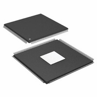
IC DSP 32BIT 266MHZ 208-LQFP
Manufacturer
Analog Devices Inc
Series
SHARC®r
Type
Floating Pointr
Specifications of ADSP-21371KSWZ-2B
Package / Case
208-LQFP
Interface
DAI, DPI
Operating Temperature
0°C ~ 70°C
Clock Rate
266MHz
Non-volatile Memory
ROM (512 kB)
On-chip Ram
128kB
Voltage - I/o
3.30V
Voltage - Core
1.20V
Mounting Type
Surface Mount
Svhc
No SVHC (18-Jun-2010)
Base Number
21371
Core Frequency Typ
266MHz
Dsp Type
Floating Point
Mmac
532
No. Of Pins
208
Interface Type
SPI, UART
Rohs Compliant
Yes
Operating Temperature Range
0°C To +70°C
Lead Free Status / RoHS Status
Lead free / RoHS Compliant
Available stocks
Company
Part Number
Manufacturer
Quantity
Price
Company:

Part Number:
ADSP-21371KSWZ-2B
Manufacturer:
Analog Devices Inc
Quantity:
10 000
Part Number:
ADSP-21371KSWZ-2B
Manufacturer:
ADI/亚德诺
Quantity:
20 000


SDRAM Controller
The SDRAM controller provides an interface to up to four sepa
rate banks of industry-standard SDRAM devices or DIMMs.
Fully compliant with the SDRAM standard, each bank can has
its own memory select line (MS0–MS3), and can be configured
to contain between 16M bytes and 128M bytes of memory.
SDRAM external memory address space is shown in
The controller maintains all of the banks as a contiguous
address space so that the processor sees this as a single address
space, even if different size devices are used in the different
banks.
A set of programmable timing parameters is available to config
ure the SDRAM banks to support slower memory devices. The
memory banks can be configured as 16 bits wide or as 32 bits
wide.
The SDRAM controller address, data, clock, and command pins
can drive loads up to 30 pF. For larger memory systems, the
SDRAM controller external buffer timing should be selected
and external buffering should be provided so that the load on
the SDRAM controller pins does not exceed 30 pF.
Table 3. External Memory for Non SDRAM Addresses
Table 4. External Memory for SDRAM Addresses
Note that the external memory bank addresses shown are for
normal word accesses. If 48-bit instructions are placed in any
such bank (with two instructions packed into three 32-bit loca
tions), then care must be taken to map data buffers in the same
bank. For example, if 2k instructions are placed starting at the
bank 0 base address (0x0020 0000), then the data buffers can be
placed starting at an address that is offset by 3k words
(0x0020 0C00).
Asynchronous Controller
The asynchronous memory controller provides a configurable
interface for up to four separate banks of memory or I/O
devices. Each bank can be independently programmed with dif
Bank
Bank 0
Bank 1
Bank 2
Bank 3
Bank
Bank 0
Bank 1
Bank 2
Bank 3
Size in
Words
14M
16M
16M
16M
Size in
Words
62M
64M
64M
64M
Address Range
0x0020 0000 – 0x00FF FFFF
0x0400 0000 – 0x04FF FFFF
0x0800 0000 – 0x08FF FFFF
0x0C00 0000 – 0x0CFF FFFF
Address Range
0x0020 0000 – 0x03FF FFFF
0x0400 0000 – 0x07FF FFFF
0x0800 0000 – 0x0BFF FFFF
0x0C00 0000 – 0x0FFF FFFF
Rev. 0 | Page 7 of 48 | June 2007
Table
4.
ferent timing parameters, enabling connection to a wide variety
of memory devices including SRAM, ROM, flash, and EPROM,
as well as I/O devices that interface with standard memory con
trol lines. Bank 0 occupies a 14.7M word window and banks 1, 2,
and 3 occupy a 16M word window in the processor’s address
space but, if not fully populated, these windows are not made
contiguous by the memory controller logic. The banks can also
be configured as 8-bit or 16-bit wide buses for ease of interfac
ing to a range of memories and I/O devices tailored either to
high performance or to low cost and power.
The asynchronous memory controller is capable of a maximum
throughput of 176 Mbps using a 44 MHz external bus speed.
Other features include 8 to 32-bit and 16 to 32-bit packing and
unpacking, booting from bank select 1, and support for delay
line DMA.
ADSP-21371 INPUT/OUTPUT FEATURES
The ADSP-21371 I/O processor provides 32 channels of DMA,
as well as an extensive set of peripherals. These include a 20 lead
digital applications interface, which controls:
The ADSP-21371 processor also contains a 14 lead digital
peripheral interface, which controls:
DMA Controller
The ADSP-21371’s on-chip DMA controller allows data trans
fers without processor intervention. The DMA controller
operates independently and invisibly to the processor core,
allowing DMA operations to occur while the core is simulta
neously executing its program instructions. DMA transfers can
occur between the ADSP-21371’s internal memory and its serial
ports, the SPI-compatible (serial peripheral interface) ports, the
IDP (input data port), the parallel data acquisition port (PDAP)
or the UART. Thirty-two channels of DMA are available on the
ADSP-21371, 16 via the serial ports, eight via the input data
port, two for the UART, two for the SPI interface, two for the
external port, and two for memory-to-memory transfers. Pro
grams can be downloaded to the ADSP-21371 using DMA
transfers. Other DMA features include interrupt generation
upon completion of DMA transfers, and DMA chaining for
automatic linked DMA transfers.
Delay Line DMA
The ADSP-21371 processor provides delay line DMA function
ality. This allows processor reads and writes to external delay
line buffers (and hence to external memory) with limited core
interaction.
• Eight serial ports
• S/PDIF receiver/transmitter
• Four precision clock generators
• Input data port/parallel data acquisition port
• Two general-purpose timers
• Two serial peripheral interfaces
• One universal asynchronous receiver/transmitter (UART)
• An I
2
C
®
-compatible 2-wire interface
ADSP-21371
Related parts for ADSP-21371KSWZ-2B
Image
Part Number
Description
Manufacturer
Datasheet
Request
R

Part Number:
Description:
±1.7g Dual-Axis IMEMS Accelerometer Evaluation Board
Manufacturer:
Analog Devices Inc
Datasheet:

Part Number:
Description:
Inertial Sensor Evaluation System
Manufacturer:
Analog Devices Inc
Datasheet:
Part Number:
Description:
Manufacturer:
Analog Devices Inc
Datasheet:
Part Number:
Description:
Manufacturer:
Analog Devices Inc
Datasheet:
Part Number:
Description:
Manufacturer:
Analog Devices Inc
Datasheet:
Part Number:
Description:
Manufacturer:
Analog Devices Inc
Datasheet:
Part Number:
Description:
Manufacturer:
Analog Devices Inc
Datasheet:
Part Number:
Description:
Manufacturer:
Analog Devices Inc
Datasheet:
Part Number:
Description:
Manufacturer:
Analog Devices Inc
Datasheet:
Part Number:
Description:
Manufacturer:
Analog Devices Inc
Datasheet:
Part Number:
Description:
Manufacturer:
Analog Devices Inc
Datasheet:
Part Number:
Description:
Manufacturer:
Analog Devices Inc
Datasheet:
Part Number:
Description:
Manufacturer:
Analog Devices Inc
Datasheet: