EP2C35F672C8N Altera, EP2C35F672C8N Datasheet - Page 148
EP2C35F672C8N
Manufacturer Part Number
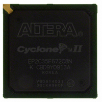
EP2C35F672C8N
Description
IC CYCLONE II FPGA 33K 672-FBGA
Manufacturer
Altera
Series
Cyclone® IIr
Datasheet
1.EP2C5T144C8N.pdf
(168 pages)
Specifications of EP2C35F672C8N
Number Of Logic Elements/cells
33216
Number Of Labs/clbs
2076
Total Ram Bits
483840
Number Of I /o
475
Voltage - Supply
1.15 V ~ 1.25 V
Mounting Type
Surface Mount
Operating Temperature
0°C ~ 85°C
Package / Case
672-FBGA
No. Of Logic Blocks
2076
Family Type
Cyclone II
No. Of I/o's
475
I/o Supply Voltage
3.3V
Operating Frequency Max
320MHz
Operating Temperature Range
0°C To +85°C
Rohs Compliant
Yes
For Use With
NANO-CYCLONE - KIT NANOBOARD AND CYCLONEII DC807-1002 - DAUGHTER CARD ALTERA CYCLONE IIP0301 - DE2 CALL FOR ACADEMIC PRICING544-1733 - PCI KIT W/CYCLONE II EP2C35N
Lead Free Status / RoHS Status
Lead free / RoHS Compliant
Number Of Gates
-
Other names
544-1692
Available stocks
Company
Part Number
Manufacturer
Quantity
Price
Company:

Part Number:
EP2C35F672C8N
Manufacturer:
YAGEO
Quantity:
500 000
Company:
Part Number:
EP2C35F672C8N
Manufacturer:
ALTERA
Quantity:
500
Part Number:
EP2C35F672C8N
Manufacturer:
ALTERA/阿尔特拉
Quantity:
20 000


Timing Specifications
5–58
Cyclone II Device Handbook, Volume 1
Note to
(1)
TCCS
Output
jitter (peak
to peak)
t
t
t
R I S E
F A L L
L O C K
Table 5–48. RSDS Transmitter Timing Specification (Part 2 of 2)
Symbol
These specifications are for a three-resistor RSDS implementation. For single-resistor RSDS in ×10 through ×2
modes, the maximum data rate is 170 Mbps and the corresponding maximum input clock frequency is 85 MHz.
For single-resistor RSDS in ×1 mode, the maximum data rate is 170 Mbps, and the maximum input clock frequency
is 170 MHz. For more information about the different RSDS implementations, refer to the
Interfaces in Cyclone II Devices
Table
20–80%,
C
80–20%,
C
5–48:
L O A D
L O A D
Conditions
—
—
—
= 5 pF
= 5 pF
In order to determine the transmitter timing requirements, RSDS receiver
timing requirements on the other end of the link must be taken into
consideration. RSDS receiver timing parameters are typically defined as
t
specifications are t
for the timing budget.
The AC timing requirements for RSDS are shown in
Min
SU
—
—
—
—
—
–6 Speed Grade
chapter of the Cyclone II Device Handbook.
and t
Typ
500
500
—
—
H
requirements. Therefore, the transmitter timing parameter
Max(1)
200
500
100
—
—
CO
(minimum) and t
Min
—
—
—
—
—
–7 Speed Grade
Typ
500
500
—
—
Max(1)
500
100
200
—
—
CO
(maximum). Refer to
Min
—
—
—
—
—
–8 Speed Grade
Typ
500
500
—
—
—
High-Speed Differential
Figure
Altera Corporation
Max(1)
February 2008
500
100
200
5–5.
—
—
Figure 5–4
Unit
ps
ps
ps
ps
μs
Related parts for EP2C35F672C8N
Image
Part Number
Description
Manufacturer
Datasheet
Request
R

Part Number:
Description:
CYCLONE II STARTER KIT EP2C20N
Manufacturer:
Altera
Datasheet:


Part Number:
Description:
CPLD, EP610 Family, ECMOS Process, 300 Gates, 16 Macro Cells, 16 Reg., 16 User I/Os, 5V Supply, 35 Speed Grade, 24DIP
Manufacturer:
Altera Corporation
Datasheet:
Part Number:
Description:
CPLD, EP610 Family, ECMOS Process, 300 Gates, 16 Macro Cells, 16 Reg., 16 User I/Os, 5V Supply, 15 Speed Grade, 24DIP
Manufacturer:
Altera Corporation
Datasheet:
Part Number:
Description:
Manufacturer:
Altera Corporation
Datasheet:
Part Number:
Description:
CPLD, EP610 Family, ECMOS Process, 300 Gates, 16 Macro Cells, 16 Reg., 16 User I/Os, 5V Supply, 30 Speed Grade, 24DIP
Manufacturer:
Altera Corporation
Datasheet:
Part Number:
Description:
High-performance, low-power erasable programmable logic devices with 8 macrocells, 10ns
Manufacturer:
Altera Corporation
Datasheet:
Part Number:
Description:
High-performance, low-power erasable programmable logic devices with 8 macrocells, 7ns
Manufacturer:
Altera Corporation
Datasheet:
Part Number:
Description:
Classic EPLD
Manufacturer:
Altera Corporation
Datasheet:
Part Number:
Description:
High-performance, low-power erasable programmable logic devices with 8 macrocells, 10ns
Manufacturer:
Altera Corporation
Datasheet:
Part Number:
Description:
Manufacturer:
Altera Corporation
Datasheet:
Part Number:
Description:
Manufacturer:
Altera Corporation
Datasheet:
Part Number:
Description:
Manufacturer:
Altera Corporation
Datasheet:
Part Number:
Description:
CPLD, EP610 Family, ECMOS Process, 300 Gates, 16 Macro Cells, 16 Reg., 16 User I/Os, 5V Supply, 25 Speed Grade, 24DIP
Manufacturer:
Altera Corporation
Datasheet: