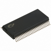
CY7C68013-56PVC Cypress Semiconductor Corp, CY7C68013-56PVC Datasheet - Page 15

CY7C68013-56PVC
Manufacturer Part Number
CY7C68013-56PVC
Description
IC MCU USB PERIPH HI SPD 56SSOP
Manufacturer
Cypress Semiconductor Corp
Series
EZ-USB FX2LP™r
Datasheet
1.CY7C68013-56PVC.pdf
(52 pages)
Specifications of CY7C68013-56PVC
Applications
USB Microcontroller
Core Processor
8051
Program Memory Type
ROMless
Controller Series
CY7C680xx
Ram Size
16K x 8
Interface
I²C, USB, USART
Number Of I /o
24
Voltage - Supply
3 V ~ 3.6 V
Operating Temperature
0°C ~ 70°C
Mounting Type
Surface Mount
Package / Case
56-SSOP
Lead Free Status / RoHS Status
Contains lead / RoHS non-compliant
Other names
428-1332
Available stocks
Company
Part Number
Manufacturer
Quantity
Price
Company:
Part Number:
CY7C68013-56PVC
Manufacturer:
CY
Quantity:
5 530
Company:
Part Number:
CY7C68013-56PVC
Manufacturer:
CY
Quantity:
6 100
Part Number:
CY7C68013-56PVC
Manufacturer:
CYPRESS/赛普拉斯
Quantity:
20 000
3.12.4
Endpoints 0 and 1 are the same for every configuration. Endpoint 0 is the only CONTROL endpoint, and endpoint 1 can be either
BULK or INTERRUPT. To the left of the vertical line, the user may pick different configurations for EP2&4 and EP6&8, since none
of the 512-byte buffers are combined between these endpoint groups. An example endpoint configuration would be:
EP2—1024 double buffered; EP6—512 quad buffered.
To the right of the vertical line, buffers are shared between EP2–8, and therefore only entire columns may be chosen.
3.12.5
Table 3-5. Default Full-Speed Alternate Settings
Notes:
Document #: 38-08012 Rev. *C
1.
2.
ep0
ep1out
ep1in
ep2
ep4
ep6
ep8
“0” means “not implemented.”
“2x” means “double buffered.”
Alternate Setting
Endpoint Configurations (High-speed Mode)
Default Full-Speed Alternate Settings
EP0 IN&OUT
EP1 OUT
EP1 IN
EP2
EP4
EP6
EP8
512
512
512
512
512
512
512
512
64
64
64
EP2
EP6
64
0
0
0
0
0
0
0
512
512
512
512
512
512
512
512
64
64
64
64
64 bulk
64 bulk
64 bulk out (2×)
64 bulk out (2×)
64 bulk in (2×)
64 bulk in (2×)
Figure 3-3. Endpoint Configuration
EP2
EP6
[1, 2]
1
1024
1024
1024
1024
64
64
64
EP8
EP2
EP6
64
64 int
64 int
64 int out (2×)
64 bulk out (2×)
64 int in (2×)
64 bulk in (2×)
64
64
64
512
512
512
512
512
512
512
512
EP2
EP8
2
1024
1024
1024
64
64
64
512
512
EP2
64
64 int
64 int
64 iso out (2×)
64 bulk out (2×)
64 iso in (2×)
64 bulk in (2×)
1024
1024
1024
1024
64
64
64
CY7C68013
3
Page 15 of 52


