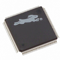
20-668-0024 Rabbit Semiconductor, 20-668-0024 Datasheet - Page 190

20-668-0024
Manufacturer Part Number
20-668-0024
Description
IC CPU RABBIT4000 128-LQFP
Manufacturer
Rabbit Semiconductor
Datasheet
1.20-668-0024.pdf
(358 pages)
Specifications of 20-668-0024
Processor Type
Rabbit 4000 8-bit
Speed
60MHz
Voltage
2.5V, 2.7V, 3V, 3.3V
Mounting Type
Surface Mount
Package / Case
128-LQFP
Lead Free Status / RoHS Status
Lead free / RoHS Compliant
Features
-
Other names
20-668-0022
316-1078
316-1078
Available stocks
Company
Part Number
Manufacturer
Quantity
Price
Company:
Part Number:
20-668-0024
Manufacturer:
Rabbit Semiconductor
Quantity:
10 000
- Current page: 190 of 358
- Download datasheet (4Mb)
When a DMA transfer is occurring, normal code execution will not occur until the transfer
is completed. To prevent DMA transfers from excessively blocking interrupts or otherwise
interfering with normal code execution, two options can be set in DMTCR. First, the max-
imum limit of a DMA transfer can be set from 1 to 64 bytes, which sets an upper limit on
interrupt latency arising from a DMA transfer. Second, the minimum number of clocks
before the DMA can be active again can be set from 12 to 512 clocks, guaranteeing
processing time for the application.
The values providing roughly equal access to the memory bus for both the processor and
the DMA is eight bytes per burst and 64 clocks between bursts.
When starting up, the DMA requires several cycles of overhead. This overhead comes
about because the DMA actually uses part of the processor to perform the data transfers,
and consists of one instruction fetch time plus three clock cycles. The byte fetched during
the instruction fetch time is discarded, and will be refetched at the completion of the DMA
burst. At the end of the DMA burst, two clock cycles are required before this first instruc-
tion fetch starts. An individual DMA channel transfers data without any overhead between
bytes, but there is always one clock cycle of dead time when switching between DMA
channels. Table 19-3 shows the number of clock cycles required per burst, assuming a sin-
gle DMA channel transfer and no wait states.
The total number of clocks listed in Table 19-3 is related to the number of bystes per burst
by the following formula.
180
Total Clocks = 4 × Number of Bytes per Burst + 7 (for overhead)
16 bytes per burst
32 bytes per burst
64 bytes per burst
2 bytes per burst
3 bytes per burst
4 bytes per burst
8 bytes per burst
1 byte per burst
Setting
Table 19-3. Maximum DMA Transfer Rates
Total Clocks
135 clocks
263 clocks
11 clocks
15 clocks
19 clocks
23 clocks
39 clocks
71 clocks
Rabbit 4000 Microprocessor User’s Manual
Clocks per Byte
Transferred
7.5
6.3
5.8
4.9
4.4
4.2
4.1
11
Related parts for 20-668-0024
Image
Part Number
Description
Manufacturer
Datasheet
Request
R

Part Number:
Description:
IC CPU RABBIT2000 30MHZ 100PQFP
Manufacturer:
Rabbit Semiconductor
Datasheet:

Part Number:
Description:
IC MPU RABIT3000A 55.5MHZ128LQFP
Manufacturer:
Rabbit Semiconductor
Datasheet:

Part Number:
Description:
Microprocessors - MPU Rabbit 3000 TFBGA Microprocessor
Manufacturer:
Rabbit Semiconductor

Part Number:
Description:
Microprocessors - MPU Rabbit 4000 LQFP Microprocessor
Manufacturer:
Rabbit Semiconductor

Part Number:
Description:
IC, I/O EXPANDER, 8BIT, 40MHZ, TQFP-64
Manufacturer:
Rabbit Semiconductor

Part Number:
Description:
SCRs 1.5A 200uA 400V Sensing
Manufacturer:
Littelfuse Inc
Datasheet:

Part Number:
Description:
CARD 6-RELAY SMARTSTAR SR9500
Manufacturer:
Rabbit Semiconductor
Datasheet:

Part Number:
Description:
WIRE-BOARD CONN RECEPTACLE, 6POS, 3.96MM
Manufacturer:
TE Connectivity
Datasheet:

Part Number:
Description:
ADAPTER 20 PIN .420" PLUGS(6PCS)
Manufacturer:
Logical Systems Inc.
Datasheet:

Part Number:
Description:
CONN BARRIER BLOCK .438" 20 POS
Manufacturer:
Cinch Connectors
Datasheet:

Part Number:
Description:
20 MODII 2PC HDR DR SHRD, ROHS
Manufacturer:
TE Connectivity
Datasheet:

Part Number:
Description:
WIRE-BOARD CONN RECEPTACLE, 6POS, 3.96MM
Manufacturer:
TE Connectivity
Datasheet:


