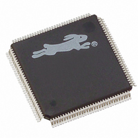
20-668-0024 Rabbit Semiconductor, 20-668-0024 Datasheet - Page 37

20-668-0024
Manufacturer Part Number
20-668-0024
Description
IC CPU RABBIT4000 128-LQFP
Manufacturer
Rabbit Semiconductor
Datasheet
1.20-668-0024.pdf
(358 pages)
Specifications of 20-668-0024
Processor Type
Rabbit 4000 8-bit
Speed
60MHz
Voltage
2.5V, 2.7V, 3V, 3.3V
Mounting Type
Surface Mount
Package / Case
128-LQFP
Lead Free Status / RoHS Status
Lead free / RoHS Compliant
Features
-
Other names
20-668-0022
316-1078
316-1078
Available stocks
Company
Part Number
Manufacturer
Quantity
Price
Company:
Part Number:
20-668-0024
Manufacturer:
Rabbit Semiconductor
Quantity:
10 000
- Current page: 37 of 358
- Download datasheet (4Mb)
3.3 Operation
Pulling the /RESET pin low will initialize everything in the Rabbit 4000 except for the
real-time clock registers and the onchip-encryption RAM. The reset of the Rabbit 4000 is
delayed until the completion of any write cycles in progress; reset takes effect immedi-
ately when no write cycles are occurring. The reset sequence requires a minimum of 128
cycles of the main clock to complete in either case.
During reset, the impedance of the /CS1 pin is high and all other memory and I/O control
signals are held high. The special behavior of /CS1 allows an external RAM to be powered
by the same source as the VBATIO pin (which powers /CS1). In this case, a pullup resistor
is required on /CS1 to keep the RAM deselected during powerdown. The RESOUT pin is
high during reset and powerdown, but low at all other times, and can be used to control an
external power switch to disconnect VDDIO from VBATIO when the main power source
is removed.
Table 3-1 lists the condition of the processor after reset takes place. The state of all regis-
ters after reset is provided in the chapter describing the specific peripheral.
The processor checks the SMODE pins after the /RESET signal is inactive. Table 3-2
summarizes what happens:
• If both SMODE pins are zero, the Rabbit 4000 begins fetching instructions from the
Chapter 3 Reset and Bootstrap
memory device on /CS0 and /OE0. If a 16-bit memory is used on /CS0, the first section
of code must immediately select the 16-bit bus mode. Chapter 5 provides a short pro-
gram to do this.
Memory Advanced
PC, SP, IIR, EIR,
Peripheral Clock
Interrupt Priority
Watchdog Timer
Watchdog Timer
Control Register
Control Register
Memory Bank 0
CPU Registers:
Clock Doubler,
Clock Dither
(IP Register)
CPU Clock,
Function
Secondary
SU, HTR
Table 3-1. Rabbit 4000 Condition After Reset
/CS0, /OE0, write-protected,
Operation After Reset
Enabled (2 seconds)
Divide-by-8 mode
0xFF (Priority 3)
8-bit interface
4 wait states
Disabled
Disabled
0x0000
27
Related parts for 20-668-0024
Image
Part Number
Description
Manufacturer
Datasheet
Request
R

Part Number:
Description:
IC CPU RABBIT2000 30MHZ 100PQFP
Manufacturer:
Rabbit Semiconductor
Datasheet:

Part Number:
Description:
IC MPU RABIT3000A 55.5MHZ128LQFP
Manufacturer:
Rabbit Semiconductor
Datasheet:

Part Number:
Description:
Microprocessors - MPU Rabbit 3000 TFBGA Microprocessor
Manufacturer:
Rabbit Semiconductor

Part Number:
Description:
Microprocessors - MPU Rabbit 4000 LQFP Microprocessor
Manufacturer:
Rabbit Semiconductor

Part Number:
Description:
IC, I/O EXPANDER, 8BIT, 40MHZ, TQFP-64
Manufacturer:
Rabbit Semiconductor

Part Number:
Description:
SCRs 1.5A 200uA 400V Sensing
Manufacturer:
Littelfuse Inc
Datasheet:

Part Number:
Description:
CARD 6-RELAY SMARTSTAR SR9500
Manufacturer:
Rabbit Semiconductor
Datasheet:

Part Number:
Description:
WIRE-BOARD CONN RECEPTACLE, 6POS, 3.96MM
Manufacturer:
TE Connectivity
Datasheet:

Part Number:
Description:
ADAPTER 20 PIN .420" PLUGS(6PCS)
Manufacturer:
Logical Systems Inc.
Datasheet:

Part Number:
Description:
CONN BARRIER BLOCK .438" 20 POS
Manufacturer:
Cinch Connectors
Datasheet:

Part Number:
Description:
20 MODII 2PC HDR DR SHRD, ROHS
Manufacturer:
TE Connectivity
Datasheet:

Part Number:
Description:
WIRE-BOARD CONN RECEPTACLE, 6POS, 3.96MM
Manufacturer:
TE Connectivity
Datasheet:


