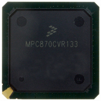
MPC870CVR133 Freescale Semiconductor, MPC870CVR133 Datasheet - Page 15

MPC870CVR133
Manufacturer Part Number
MPC870CVR133
Description
IC MPU POWERQUICC 133MHZ 256PBGA
Manufacturer
Freescale Semiconductor
Series
PowerQUICCr
Datasheet
1.MPC870VR80.pdf
(84 pages)
Specifications of MPC870CVR133
Processor Type
MPC8xx PowerQUICC 32-Bit
Speed
133MHz
Voltage
3.3V
Mounting Type
Surface Mount
Package / Case
256-PBGA
Processor Series
MPC8xx
Core
MPC8xx
Data Bus Width
32 bit
Maximum Clock Frequency
133 MHz
Operating Supply Voltage
0 V to 5 V
Maximum Operating Temperature
+ 100 C
Mounting Style
SMD/SMT
Data Ram Size
8 KB
I/o Voltage
5 V
Interface Type
I2C, SPI, UART
Minimum Operating Temperature
- 40 C
Program Memory Size
8 KB
Program Memory Type
EPROM/Flash
Core Size
32 Bit
Cpu Speed
133MHz
Digital Ic Case Style
BGA
No. Of Pins
256
Supply Voltage Range
1.7V To 1.9V
Rohs Compliant
Yes
Lead Free Status / RoHS Status
Lead free / RoHS Compliant
Features
-
Lead Free Status / Rohs Status
Lead free / RoHS Compliant
Available stocks
Company
Part Number
Manufacturer
Quantity
Price
Company:
Part Number:
MPC870CVR133
Manufacturer:
Freescale
Quantity:
560
Company:
Part Number:
MPC870CVR133
Manufacturer:
Freescale Semiconductor
Quantity:
10 000
One consequence of multiple power supplies is that when power is initially applied, the voltage rails ramp
up at different rates. The rates depend on the nature of the power supply, the type of load on each power
supply, and the manner in which different voltages are derived. The following restrictions apply:
These cautions are necessary for the long-term reliability of the part. If they are violated, the electrostatic
discharge (ESD) protection diodes are forward-biased, and excessive current can flow through these
diodes. If the system power supply design does not control the voltage sequencing, the circuit shown in
Figure 4
potential difference between the external bus and core power supplies on power up, and the 1N5820 diodes
regulate the maximum potential difference on power down.
9
The MPC875/MPC870 requires a mandatory configuration during reset.
If hardware reset configuration word (HRCW) is enabled, the HRCW[DBGC] value needs to be set to
binary X1 in the HRCW and the SIUMCR[DBGC] should be programmed with the same value in the boot
code after reset. This can be done by asserting the RSTCONF during HRESET assertion.
If HRCW is disabled, the SIUMCR[DBGC] should be programmed with binary X1 in the boot code after
reset by negating the RSTCONF during the HRESET assertion.
The MBMR[GPLB4DIS], PAPAR, PADIR, PBPAR, PBDIR, PCPAR, and PCDIR need to be configured
with the mandatory values in
Freescale Semiconductor
HRCW (Hardware reset configuration word)
SIUMCR (SIU module configuration register)
MBMR (Machine B mode register)
PAPAR (Port A pin assignment register)
•
•
V
V
Mandatory Reset Configurations
can be added to meet these requirements. The MUR420 Schottky diodes control the maximum
DDL
DDL
must not exceed V
must not exceed 1.9 V, and V
Table 7. Mandatory Reset Configuration of MPC875/MPC870
MPC875/MPC870 PowerQUICC™ Hardware Specifications, Rev. 4
Register/Configuration
Table 7
Figure 4. Example Voltage Sequencing Circuit
DDH
V
during power up and power down
DDH
in the boot code after the reset is negated.
DDH
MUR420
must not exceed 3.465 V
1N5820
V
DDL
HRCW[DBGC]
SIUMCR[DBGC]
MBMR[GPLB4DIS}
PAPAR[5:9]
PAPAR[12:13]
Mandatory Reset Configurations
Field
(Binary)
Value
X1
X1
0
0
15


