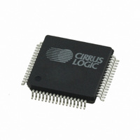
CS42416-DQZR Cirrus Logic Inc, CS42416-DQZR Datasheet - Page 43

CS42416-DQZR
Manufacturer Part Number
CS42416-DQZR
Description
IC CODEC 6CH 110DB 192KHZ 64LQFP
Manufacturer
Cirrus Logic Inc
Type
Audio Codecr
Datasheet
1.CS42416-CQZ.pdf
(73 pages)
Specifications of CS42416-DQZR
Package / Case
64-LQFP
Data Interface
Serial
Resolution (bits)
24 b
Number Of Adcs / Dacs
2 / 6
Sigma Delta
Yes
Dynamic Range, Adcs / Dacs (db) Typ
114 / 110
Voltage - Supply, Analog
4.75 V ~ 5.25 V
Voltage - Supply, Digital
3.13 V ~ 5.25 V
Operating Temperature
-40°C ~ 85°C
Mounting Type
Surface Mount
Number Of Adc Inputs
2
Number Of Dac Outputs
6
Conversion Rate
192 KSPs
Interface Type
Serial (I2C, SPI)
Resolution
24 bit
Maximum Operating Temperature
+ 85 C
Mounting Style
SMD/SMT
Minimum Operating Temperature
- 40 C
Number Of Channels
2 ADC, 6 DAC
Lead Free Status / RoHS Status
Lead free / RoHS Compliant
Available stocks
Company
Part Number
Manufacturer
Quantity
Price
Company:
Part Number:
CS42416-DQZR
Manufacturer:
Cirrus Logic Inc
Quantity:
10 000
DS602F1
6.3
6.3.1
6.3.2
6.3.3
6.3.4
6.4
6.4.1
DAC_FM1
Reserved
7
7
Power Control (address 02h)
POWER DOWN PLL (PDN_PLL)
POWER DOWN ADC (PDN_ADC)
POWER DOWN DAC PAIRS (PDN_DACX)
POWER DOWN (PDN)
Functional Mode (address 03h)
DAC FUNCTIONAL MODE (DAC_FMX)
Selects the required range of sample rates for all converters clocked from the DAC serial port (DAC_SP).
Bits must be set to the corresponding sample rate range when the DAC_SP is in Master or Slave Mode.
Default = 0
Function:
Default = 0
Function:
Default = 0
Function:
Default = 1
Function:
Default = 00
00 - Single-Speed Mode (4 to 50 kHz sample rates)
01 - Double-Speed Mode (50 to 100 kHz sample rates)
10 - Quad-Speed Mode (100 to 192 kHz sample rates)
11 - Reserved
Function:
When enabled, the PLL is held in a reset state. It is advised that any change of this bit be made while
the DACs are muted or the power-down bit (PDN) is enabled to eliminate the possibility of audible
artifacts.
When enabled the stereo analog to digital converter will remain in a reset state. It is advised that any
change of this bit be made while the DACs are muted or the power-down bit (PDN) is enabled to elim-
inate the possibility of audible artifacts.
When enabled the respective DAC channel pair x (AOUTAx and AOUTBx) will remain in a reset state.
The entire device will enter a low-power state when this function is enabled, and the contents of the
control registers are retained in this mode. The power-down bit defaults to ‘enabled’ on power-up and
must be disabled before normal operation can occur.
DAC_FM0
PDN_PLL
6
6
PDN_ADC
ADC_FM1
5
5
ADC_FM0
Reserved
4
4
PDN_DAC3
Reserved
3
3
ADC_SP SEL
PDN_DAC2
2
2
PDN_DAC1
DAC_DEM
1
1
CS42416
Reserved
PDN
0
0
43


