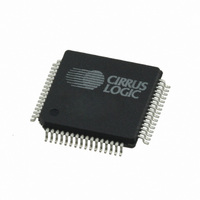
CS42416-DQZR Cirrus Logic Inc, CS42416-DQZR Datasheet - Page 47

CS42416-DQZR
Manufacturer Part Number
CS42416-DQZR
Description
IC CODEC 6CH 110DB 192KHZ 64LQFP
Manufacturer
Cirrus Logic Inc
Type
Audio Codecr
Datasheet
1.CS42416-CQZ.pdf
(73 pages)
Specifications of CS42416-DQZR
Package / Case
64-LQFP
Data Interface
Serial
Resolution (bits)
24 b
Number Of Adcs / Dacs
2 / 6
Sigma Delta
Yes
Dynamic Range, Adcs / Dacs (db) Typ
114 / 110
Voltage - Supply, Analog
4.75 V ~ 5.25 V
Voltage - Supply, Digital
3.13 V ~ 5.25 V
Operating Temperature
-40°C ~ 85°C
Mounting Type
Surface Mount
Number Of Adc Inputs
2
Number Of Dac Outputs
6
Conversion Rate
192 KSPs
Interface Type
Serial (I2C, SPI)
Resolution
24 bit
Maximum Operating Temperature
+ 85 C
Mounting Style
SMD/SMT
Minimum Operating Temperature
- 40 C
Number Of Channels
2 ADC, 6 DAC
Lead Free Status / RoHS Status
Lead free / RoHS Compliant
Available stocks
Company
Part Number
Manufacturer
Quantity
Price
Company:
Part Number:
CS42416-DQZR
Manufacturer:
Cirrus Logic Inc
Quantity:
10 000
DS602F1
6.6.4
6.6.5
6.6.6
6.6.7
INTERPOLATION FILTER SELECT (FILT_SEL)
HIGH-PASS FILTER FREEZE (HPF_FREEZE)
DAC SERIAL PORT MASTER/SLAVE SELECT (DAC_SP M/S)
ADC SERIAL PORT MASTER/SLAVE SELECT (ADC_SP M/S)
Default = 0
Function:
Default = 0
Function:
Default = 0
Function:
Default = 0
Function:
This feature allows the user to select whether the DAC interpolation filter has a fast- or slow roll-off.
For filter characteristics, please See
0 - Fast roll-off.
1 - Slow roll-off.
When this bit is set, the internal high-pass filter for the selected channel will be disabled. The current
DC offset value will be frozen and continue to be subtracted from the conversion result. See
ital Filter Characteristics” on page
In Master Mode, DAC_SCLK and DAC_LRCK are outputs. Internal dividers will divide the master
clock to generate the serial clock and left/right clock. In Slave Mode, DAC_SCLK and DAC_LRCK
become inputs.
If the DAC_SP is in Slave Mode, DAC_LRCK must be present for proper device operation.
In Master Mode, ADC_SCLK and ADC_LRCK are outputs. Internal dividers will divide the master
clock to generate the serial clock and left/right clock. In Slave Mode, ADC_SCLK and ADC_LRCK
become inputs.
If the ADC_SP is in Slave Mode, ADC_LRCK must be present for proper device operation.
To use the PLL to lock to ADC_LRCK, the ADC_SP must be in Slave Mode. When using the PLL to
lock to LRCK, if ADC_SDOUT is configured to be clocked by the ADC_SP, both ADC_SCLK and
ADC_LRCK must be present. If ADC_SDOUT is configured to be clocked by the DAC_SP, only the
ADC_LRCK signal must be applied.
8.
“D/A Digital Filter Characteristics” on page
10.
CS42416
“A/D Dig-
47


