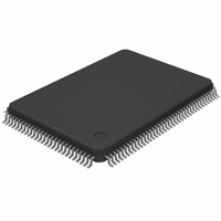
DS21Q42T+ Maxim Integrated Products, DS21Q42T+ Datasheet - Page 37

DS21Q42T+
Manufacturer Part Number
DS21Q42T+
Description
IC FRAMER ENHANCED T1 4X 128TQFP
Manufacturer
Maxim Integrated Products
Datasheet
1.DS21Q42T.pdf
(116 pages)
Specifications of DS21Q42T+
Controller Type
T1 Framer
Interface
Parallel/Serial
Voltage - Supply
2.97 V ~ 3.63 V
Current - Supply
75mA
Operating Temperature
0°C ~ 70°C
Mounting Type
Surface Mount
Package / Case
128-TQFP, 128-VQFP
Lead Free Status / RoHS Status
Lead free / RoHS Compliant
CCR7: COMMON CONTROL REGISTER 7 (Address=0A Hex)
Remote Loopback
When CCR7.6 is set to a one, the DS21Q42 will be forced into Remote LoopBack (RLB). In this
loopback, data input via the RPOS and RNEG pins will be transmitted back to the TPOS and TNEG pins.
Data will continue to pass through the receive side framer of the DS21Q42 as it would normally and the
data from the transmit side formatter will be ignored. Please see Figure 1-1 for more details.
7. STATUS AND INFORMATION REGISTERS
There is a set of nine registers per channel that contain information on the current real time status of a
framer in the DS21Q42, Status Register 1 (SR1), Status Register 2 (SR2), Receive Information Registers
1 to 3 (RIR1/RIR2/RIR3) and a set of four registers for the onboard HDLC and BOC controller. The
specific details on the four registers pertaining to the HDLC and BOC controller are covered in Section
15 but they operate the same as the other status registers in the DS21Q42 and this operation is described
below.
When a particular event has occurred (or is occurring), the appropriate bit in one of these nine registers
will be set to a one. All of the bits in SR1, SR2, RIR1, RIR2, and RIR3 registers operate in a latched
fashion. This means that if an event or an alarm occurs and a bit is set to a one in any of the registers, it
will remain set until the user reads that bit. The bit will be cleared when it is read and it will not be set
again until the event has occurred again (or in the case of the RBL, RYEL, LRCL, and RLOS alarms, the
bit will remain set if the alarm is still present). There are bits in the four HDLC and BOC status registers
that are not latched and these bits are listed in Section 15.
(MSB)
SYMBOL
RESR
-
TESR
RLB
–
–
–
–
–
RLB
POSITION
CCR7.7
CCR7.6
CCR7.5
CCR7.4
CCR7.3
CCR7.2
CCR7.1
CCR7.0
RESR
NAME AND DESCRIPTION
Not Assigned. Should be set to zero when written to.
Remote Loopback.
0 = loopback disabled
1 = loopback enabled
Receive Elastic Store Reset. Setting this bit from a zero to a one
will force the receive elastic store to a depth of one frame. Receive
data is lost during the reset. Should be toggled after RSYSCLK
has been applied and is stable. Do not leave this bit set high.
Transmit Elastic Store Reset. Setting this bit from a zero to a
one will force the transmit elastic store to a depth of one frame.
Transmit data is lost during the reset. Should be toggled after
TSYSCLK has been applied and is stable. Do not leave this bit set
high.
Not Assigned. Should be set to zero when written to.
Not Assigned. Should be set to zero when written to.
Not Assigned. Should be set to zero when written to.
Not Assigned. Should be set to zero when written to.
TESR
37 of 116
-
-
-
(LSB)
-


