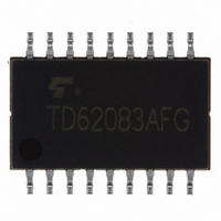
TD62083AFG(5,S) Toshiba, TD62083AFG(5,S) Datasheet

TD62083AFG(5,S)
Specifications of TD62083AFG(5,S)
TD62083AFG(5S)
TD62083AFG(O,N)
TD62083AFG(O,N)
TD62083AFG5S
TD62083AFG5S
TD62083AFGON
TD62083AFGON
Related parts for TD62083AFG(5,S)
TD62083AFG(5,S) Summary of contents
Page 1
... Toshiba Bipolar Digital Integrated Circuit Silicon Monolithic TD62081APG,TD62081AFG,TD62082APG,TD62082AFG, TD62083APG,TD62083AFG,TD62084APG,TD62084AFG 8ch Darlington Sink Driver The TD62081APG/AFG Series are high-voltage, high-current darlington drivers comprised of eight NP darlington pairs. All units feature integral clamp diodes for switching inductive loads. Applications include relay, hammer, lamp and display (LED) drivers ...
Page 2
Schematics (each driver) TD62081APG/AFG Common Input Output 7.2 kΩ GND TD62084APG/AFG Common Input Output 10.5 kΩ 7.2 kΩ GND Note: The input and output parasitic diodes cannot be used as clamp diodes. Absolute Maximum Ratings Characteristics Output sustaining voltage Output ...
Page 3
Recommended Operating Conditions Characteristics Output sustaining voltage APG Output current AFG Except Input voltage TD62081APG/AFG TD62082APG/AFG Input voltage TD62083APG/AFG (Output on) TD62084APG/AFG TD62082APG/AFG Input voltage TD62083APG/AFG (Output off) TD62084APG/AFG Only Input current TD62081APG/AFG Clamp diode reverse voltage Clamp diode forward ...
Page 4
Electrical Characteristics Characteristics Output leakage current TD62082 TD62084 Collector-emitter saturation voltage TD62082APG/AFG TD62083APG/AFG Input current TD62084APG/AFG TD62082APG/AFG TD62083APG/AFG Input voltage (Output on) TD62084APG/AFG DC current transfer ratio Clamp diode reverse current Clamp diode forward voltage Input capacitance ...
Page 5
Test Circuit 1. I CEX Open I CEX Open (OFF) Open (OFF) OUT Open Open (sat) ...
Page 6
ON, OFF Pulse generator (Note 1) Input 50% 10% t Output Note 1: Pulse width 50 µs, duty cycle 10% Output impedance 50 Ω Note 2: See below. Input condition Type Number TD62081APG/AFG TD62082APG/AFG TD62083APG/AFG ...
Page 7
I – TD62082APG 2 max typ. 1 min Input voltage V ( – TD62084APG 2 max 1 typ. min Input ...
Page 8
I FE OUT 10000 TD62083 5000 2.0 V 3000 1000 85°C 500 −40 300 100 100 1000 Output current I (mA) OUT P – 2.0 ...
Page 9
Package Dimensions Weight: 1.47 g (typ.) TD62081~084APG/AFG 9 2006-06-13 ...
Page 10
Package Dimensions Weight: 0.41 g (typ.) TD62081~084APG/AFG 10 2006-06-13 ...
Page 11
Notes on Contents 1. Equivalent Circuits The equivalent circuit diagrams may be simplified or some parts of them may be omitted for explanatory purposes. 2. Test Circuits Components in the test circuits are used only to obtain and confirm the ...
Page 12
Points to Remember on Handling of ICs (1) Heat Radiation Design In using an IC with large current flow such as power amp, regulator or driver, please design the device so that heat is appropriately radiated, not to exceed the ...
Page 13
... TOSHIBA is continually working to improve the quality and reliability of its products. Nevertheless, semiconductor devices in general can malfunction or fail due to their inherent electrical sensitivity and vulnerability to physical stress the responsibility of the buyer, when utilizing TOSHIBA products, to comply with the standards of safety in making a safe design for the entire system, and to avoid situations in which a malfunction or failure of such TOSHIBA products could cause loss of human life, bodily injury or damage to property ...


