DS2148T+ Maxim Integrated Products, DS2148T+ Datasheet - Page 4
DS2148T+
Manufacturer Part Number
DS2148T+
Description
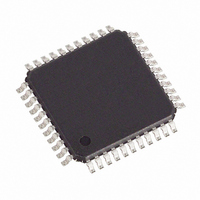
IC LIU E1/T1/J1 5V 44-TQFP
Manufacturer
Maxim Integrated Products
Type
Line Interface Units (LIUs)r
Specifications of DS2148T+
Number Of Drivers/receivers
1/1
Protocol
T1/E1/J1
Voltage - Supply
4.75 V ~ 5.25 V
Mounting Type
Surface Mount
Package / Case
44-TQFP, 44-VQFP
Lead Free Status / RoHS Status
Lead free / RoHS Compliant


DS2148/DS21Q48
LIST OF TABLES
Table 2-1. Bus Interface Selection ...........................................................................................................10
Table 2-2. Pin Assignment in Parallel Port Mode .....................................................................................10
Table 2-3. Pin Descriptions in Parallel Port Mode (Sorted by Pin Name, DS2148T) ...............................12
Table 2-4. Pin Assignment in Serial Port Mode ........................................................................................14
Table 2-5. Pin Descriptions in Serial Port Mode (Sorted by Pin Name, DS2148T) ..................................15
Table 2-6. Pin Assignment in Hardware Mode .........................................................................................17
Table 2-7. Pin Description in Hardware Mode (Sorted by Pin Name, DS2148T) .....................................18
Table 2-8. Loopback Control in Hardware Mode ......................................................................................20
Table 2-9. Transmit Data Control in Hardware Mode ...............................................................................20
Table 2-10. Receive Sensitivity Settings ..................................................................................................20
Table 2-11. Monitor Gain Settings ............................................................................................................20
Table 2-12. Internal Rx Termination Select ..............................................................................................20
Table 2-13. MCLK Selection.....................................................................................................................20
Table 3-1. Register Map ...........................................................................................................................23
Table 4-1. MCLK Selection.......................................................................................................................29
Table 4-2. Receive Sensitivity Settings ....................................................................................................31
Table 4-3. Backplane Clock Select...........................................................................................................32
Table 4-4. Monitor Gain Settings ..............................................................................................................32
Table 4-5. Internal Rx Termination Select ................................................................................................33
Table 5-1. Received Alarm Criteria ..........................................................................................................35
Table 5-2. Receive Level Indication .........................................................................................................38
Table 6-1. Transmit Code Length .............................................................................................................40
Table 6-2. Receive Code Length..............................................................................................................40
Table 6-3. Definition of Received Errors...................................................................................................44
Table 6-4. Function of ECRS Bits and RNEG Pin ....................................................................................45
Table 7-1. Line Build-Out Select for E1 in Register CCR4 (ETS = 0).......................................................48
Table 7-2. Line Build-Out Select for T1 in Register CCR4 (ETS = 1).......................................................48
Table 7-3. Transformer Specifications for 5V Operation ..........................................................................48
Table 8-1. DS21Q48 Pin Assignment.......................................................................................................55
Table 9-1. Recommended DC Operating Conditions ...............................................................................59
Table 9-2. Capacitance ............................................................................................................................59
Table 9-3. DC Characteristics ..................................................................................................................59
Table 9-4. Thermal Characteristics—DS21Q48 CSBGA Package...........................................................60
Table 9-5. Theta-JA (θ
) vs. Airflow ........................................................................................................60
JA
Table 10-1. AC Characteristics—Multiplexed Parallel Port (BIS1 = 0, BIS0 = 0) ....................................61
Table 10-2. AC Characteristics—Nonmultiplexed Parallel Port (BIS1 = 0, BIS0 = 1)..............................64
Table 10-3. AC Characteristics—Serial Port (BIS1 = 1, BIS0 = 0) ...........................................................67
Table 10-4. AC Characteristics—Receive Side ........................................................................................68
Table 10-5. AC Characteristics—Transmit Side .......................................................................................69
4 of 73
Related parts for DS2148T+
Image
Part Number
Description
Manufacturer
Datasheet
Request
R

Part Number:
Description:
MAX7528KCWPMaxim Integrated Products [CMOS Dual 8-Bit Buffered Multiplying DACs]
Manufacturer:
Maxim Integrated Products
Datasheet:
Part Number:
Description:
Single +5V, fully integrated, 1.25Gbps laser diode driver.
Manufacturer:
Maxim Integrated Products
Datasheet:
Part Number:
Description:
Single +5V, fully integrated, 155Mbps laser diode driver.
Manufacturer:
Maxim Integrated Products
Datasheet:
Part Number:
Description:
VRD11/VRD10, K8 Rev F 2/3/4-Phase PWM Controllers with Integrated Dual MOSFET Drivers
Manufacturer:
Maxim Integrated Products
Datasheet:
Part Number:
Description:
Highly Integrated Level 2 SMBus Battery Chargers
Manufacturer:
Maxim Integrated Products
Datasheet:
Part Number:
Description:
Current Monitor and Accumulator with Integrated Sense Resistor; ; Temperature Range: -40°C to +85°C
Manufacturer:
Maxim Integrated Products
Part Number:
Description:
TSSOP 14/A�/RS-485 Transceivers with Integrated 100O/120O Termination Resis
Manufacturer:
Maxim Integrated Products
Part Number:
Description:
TSSOP 14/A�/RS-485 Transceivers with Integrated 100O/120O Termination Resis
Manufacturer:
Maxim Integrated Products
Part Number:
Description:
QFN 16/A�/AC-DC and DC-DC Peak-Current-Mode Converters with Integrated Step
Manufacturer:
Maxim Integrated Products
Part Number:
Description:
TDFN/A/65V, 1A, 600KHZ, SYNCHRONOUS STEP-DOWN REGULATOR WITH INTEGRATED SWI
Manufacturer:
Maxim Integrated Products
Part Number:
Description:
Integrated Temperature Controller f
Manufacturer:
Maxim Integrated Products
Part Number:
Description:
SOT23-6/I�/45MHz to 650MHz, Integrated IF VCOs with Differential Output
Manufacturer:
Maxim Integrated Products
Part Number:
Description:
SOT23-6/I�/45MHz to 650MHz, Integrated IF VCOs with Differential Output
Manufacturer:
Maxim Integrated Products
Part Number:
Description:
EVALUATION KIT/2.4GHZ TO 2.5GHZ 802.11G/B RF TRANSCEIVER WITH INTEGRATED PA
Manufacturer:
Maxim Integrated Products
Part Number:
Description:
QFN/E/DUAL PCIE/SATA HIGH SPEED SWITCH WITH INTEGRATED BIAS RESISTOR
Manufacturer:
Maxim Integrated Products
Datasheet: