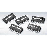
FM3264-G Ramtron, FM3264-G Datasheet - Page 17

FM3264-G
Manufacturer Part Number
FM3264-G
Description
Supervisory Circuits 64K w/Pwr Mon WDT Bat Sw Pwr Fail
Manufacturer
Ramtron
Datasheet
1.FM3264-G.pdf
(21 pages)
Specifications of FM3264-G
Number Of Voltages Monitored
4
Monitored Voltage
2.6 V or 2.9 V or 3.9 V or 4.4 V
Output Type
Active Low or Bidirectional
Manual Reset
Resettable
Watchdog
Watchdog
Battery Backup Switching
Backup
Power-up Reset Delay (typ)
200 ms
Supply Voltage (max)
5.5 V
Supply Voltage (min)
2.7 V
Supply Current (typ)
1500 uA
Maximum Operating Temperature
+ 85 C
Mounting Style
SMD/SMT
Package / Case
SOIC-14
Minimum Operating Temperature
- 40 C
Power Fail Detection
Yes
Lead Free Status / Rohs Status
Lead free / RoHS Compliant
Available stocks
Company
Part Number
Manufacturer
Quantity
Price
Company:
Part Number:
FM3264-GTR
Manufacturer:
CYPRESS
Quantity:
2 500
Notes
1.
2.
3.
4.
5.
6.
7.
8.
9.
10. V
AC Parameters
All SCL specifications as well as start and stop conditions apply to both read and write operations.
Capacitance
Notes
1
Data Retention
Rev. 3.1
July 2010
DC Operating Conditions, continued
Symbol
R
V
V
Symbol
f
t
t
t
t
t
t
t
t
t
t
t
t
t
C
Data Retention
Symbol
LOW
HIGH
AA
BUF
HD:STA
SU:STA
HD:DAT
SU:DAT
R
F
SU:STO
DH
SP
SCL
IN
IO
PFI
HYS
SCL toggling between V
All inputs at V
V
V
/RST is asserted low when V
The minimum V
Full complete operation. Supervisory circuits operate to lower voltages as specified.
Includes /RST input detection of external reset condition to trigger driving of /RST signal by FM32xx.
The VBAK trickle charger automatically regulates the maximum voltage on this pin for capacitor backup applications.
This parameter is characterized but not tested.
IN
BAK
BAK
or V
= 3.0V, V
will source current when trickle charge is enabled (VBC bit=1), V
OUT
Parameter
Input Resistance (pulldown)
Power Fail Input Reference Voltage
Power Fail Input (PFI) Hysteresis (Rising)
Parameter
SCL Clock Frequency
Clock Low Period
Clock High Period
SCL Low to SDA Data Out Valid
Bus Free Before New Transmission
Start Condition Hold Time
Start Condition Setup for Repeated
Start
Data In Hold Time
Data In Setup Time
Input Rise Time
Input Fall Time
Stop Condition Setup Time
Data Output Hold
Noise Suppression Time Constant
on SCL, SDA
Input/Output Capacitance
(T
A1-A0 for V
A1-A0 for V
= V
Parameter
A
(T
(T
SS
= 25° C, f=1.0 MHz, V
DD
A
SS
A
DD
or V
= -40° C to + 85° C, V
= -40° C to + 85° C, V
to V
< 2.4V, CNT1-2 at V
to guarantee the level of /RST remains a valid V
DD,
DD
DD
static. Stop command issued.
IN
IN
. Does not apply to A0, A1, PFI, or /RST pins.
-0.3V and V
= V
= V
DD
(from SCL @ VIL)
< V
IL
IH
Parameter
max
min
TP
.
DD
SS
BAK
(T
DD
DD
, other inputs V
= 3.0V)
A
= 2.7V to 5.5V)
.
= 2.7V to 5.5V, C
= -40° C to + 85° C, V
Min
10
Min
250
4.7
4.0
4.7
4.0
4.7
4.0
0
0
0
SS
or V
L
Max
1000
100
300
50
Years
= 100 pF unless otherwise specified)
Units
3
DD
1.175
Min
-0.3V.
20
DD
1
OL
= 2.7V to 5.5V unless otherwise specified)
level.
Min
100
1.3
0.6
1.3
0.6
0.6
0.6
DD
0
0
0
> V
Typ
-
BAK
Notes
Typ
1.20
Max
400
300
300
0.9
50
-
, and V
Max
Min
0.25
0.25
0.25
100
BAK
0.6
0.4
0.5
0
0
0
8
Continued
1.225
< V
100
BAK
1000
Max
Max
0.55
300
100
50
Units
max.
FM3204/16/64/256
pF
»
Units
Units
MΩ
KΩ
mV
kHz
V
µs
µs
µs
µs
µs
µs
ns
ns
ns
ns
µs
ns
ns
Page 17 of 21
Notes
1
Notes
Notes
1
1


