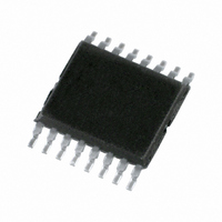
PCA9538PW,118 NXP Semiconductors, PCA9538PW,118 Datasheet - Page 7

PCA9538PW,118
Manufacturer Part Number
PCA9538PW,118
Description
IC I/O EXPANDER I2C 8B 16TSSOP
Manufacturer
NXP Semiconductors
Datasheet
1.PCA9538BS118.pdf
(28 pages)
Specifications of PCA9538PW,118
Package / Case
16-TSSOP
Interface
I²C, SMBus
Number Of I /o
8
Interrupt Output
Yes
Frequency - Clock
400kHz
Voltage - Supply
2.3 V ~ 5.5 V
Operating Temperature
-40°C ~ 85°C
Mounting Type
Surface Mount
Includes
POR
Logic Family
PCA9538
Number Of Lines (input / Output)
8.0 / 8.0
Operating Supply Voltage
2.3 V to 5.5 V
Power Dissipation
200 mW
Operating Temperature Range
- 40 C to + 85 C
Input Voltage
5 V
Logic Type
I2C, SMBus
Maximum Clock Frequency
400 KHz
Mounting Style
SMD/SMT
Number Of Input Lines
8.0
Number Of Output Lines
8.0
Output Current
50 mA
Output Voltage
5 V
Lead Free Status / RoHS Status
Lead free / RoHS Compliant
For Use With
568-3615 - DEMO BOARD I2C
Lead Free Status / Rohs Status
Lead free / RoHS Compliant
Other names
568-1840-2
935277419118
PCA9538PW-T
935277419118
PCA9538PW-T
Available stocks
Company
Part Number
Manufacturer
Quantity
Price
Company:
Part Number:
PCA9538PW,118
Manufacturer:
TI
Quantity:
2 500
NXP Semiconductors
PCA9538_5
Product data sheet
6.2.5 Register 3 - Configuration register
6.3 Power-on reset
6.4 RESET input
6.5 Interrupt output
This register configures the directions of the I/O pins. If a bit in this register is set, the
corresponding port pin is enabled as an input with high-impedance output driver. If a bit in
this register is cleared, the corresponding port pin is enabled as an output. At reset, the
I/Os are configured as inputs.
Table 7.
Legend: * default value.
When power is applied to V
a reset condition until V
and the PCA9538 registers and state machine will initialize to their default states.
Thereafter, V
For a power reset cycle, V
operating voltage.
A reset can be accomplished by holding the RESET pin LOW for a minimum of t
The PCA9538 registers and SMBus/I
state until the RESET input is once again HIGH. This input requires a pull-up resistor to
V
The open-drain interrupt output (INT) is activated when one of the port pins changes state
and the pin is configured as an input. The interrupt is de-activated when the input returns
to its previous state or the Input Port register is read.
Note that changing an I/O from an output to an input may cause a false interrupt to occur
if the state of the pin does not match the contents of the Input Port register.
Bit
7
6
5
4
3
2
1
0
DD
if no active connection is used.
Symbol
C7
C6
C5
C4
C3
C2
C1
C0
Register 3 - Configuration register bit description
DD
must be lowered below 0.2 V to reset the device.
8-bit I
Access
R/W
R/W
R/W
R/W
R/W
R/W
R/W
R/W
2
DD
Rev. 05 — 28 May 2009
C-bus and SMBus low power I/O port with interrupt and reset
DD
has reached V
DD
must be lowered below 0.2 V and then restored to the
, an internal Power-On Reset (POR) holds the PCA9538 in
Value
1*
1*
1*
1*
1*
1*
1*
1*
2
C-bus state machine will be held in their default
POR
Description
configures the directions of the I/O pins
0 = corresponding port pin enabled as an output
1 = corresponding port pin configured as an input
(default value)
. At that point, the reset condition is released
PCA9538
© NXP B.V. 2009. All rights reserved.
w(rst)
7 of 28
.


