AD694JNZ Analog Devices Inc, AD694JNZ Datasheet - Page 11
AD694JNZ
Manufacturer Part Number
AD694JNZ
Description
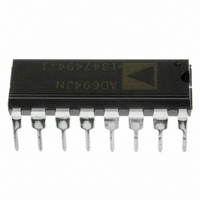
IC TRANSMITTER 4-20MA 16-DIP
Manufacturer
Analog Devices Inc
Type
Current Transmitterr
Datasheet
1.AD694JNZ.pdf
(16 pages)
Specifications of AD694JNZ
Input Type
Voltage
Output Type
Voltage
Current - Supply
23mA
Mounting Type
Through Hole
Package / Case
16-DIP (0.300", 7.62mm)
Number Of Channels
1
Number Of Elements
3
Power Supply Requirement
Single
Common Mode Rejection Ratio
80dB
Voltage Gain Db
93.98dB
Input Resistance
5@24VMohm
Input Offset Voltage
0.5@24VmV
Input Bias Current
0.005@24V@-40C TO 85nA
Single Supply Voltage (typ)
5/9/12/15/18/24/28V
Dual Supply Voltage (typ)
Not RequiredV
Power Supply Rejection Ratio
80dB
Rail/rail I/o Type
No
Single Supply Voltage (min)
4.5V
Single Supply Voltage (max)
36V
Dual Supply Voltage (min)
Not RequiredV
Dual Supply Voltage (max)
Not RequiredV
Operating Temp Range
0C to 70C
Operating Temperature Classification
Commercial
Mounting
Through Hole
Pin Count
16
Package Type
PDIP
No. Of Amplifiers
4
Bandwidth
300kHz
Amplifier Output
Differential
Cmrr
90dB
Supply Voltage Range
4.5V To 36V, 12.5V To 36V
Supply Current
2mA
Rohs Compliant
Yes
Lead Free Status / RoHS Status
Lead free / RoHS Compliant
Interface
-
Lead Free Status / Rohs Status
RoHS Compliant part
Electrostatic Device
Available stocks
Company
Part Number
Manufacturer
Quantity
Price
Company:

Part Number:
AD694JNZ
Manufacturer:
ALTERA
Quantity:
3 000
Part Number:
AD694JNZ
Manufacturer:
ADI/亚德诺
Quantity:
20 000


REV. B
code dependent, and the response time of the circuit will be de-
termined by the reaction of the voltage reference. The supply
voltage to the AD7541A should be kept close to 15 V. If V
reduced significantly from 15 V the differential nonlinearity of
the DAC will increase and the linearity will be degraded.
In some applications it is desirable to have some underrange and
overrange in the 4–20 mA output. For example, assume an over
and under range capability of ± 5% of span is needed, then the
output current range corresponding to the full scale of the DAC
is 3.2 mA to 20.8 mA. To accomplish this, the span of the
AD694 would be increased 10% to 17.6 mA by adding a nonin-
verting gain of 1.1 to the buffer amplifier. The 4 mA offset
would then be reduced by 0.8 mA, by utilizing the adjustment
scheme explained in Adjusting 4 mA Zero section. Then a digi-
tal input from all zero code to full scale would result in an out-
put current of 3.2 mA to 20.8 mA.
LOW COST SENSOR TRANSMITTER
Sensor bridges typically output differential signals in the 10 mV
to 100 mV full-scale range. With an AD694, a dual op amp, and
Figure 13. Digital to 4–20 mA Interface Using a Current Steering DAC
Figure 14. Single-Supply Digital Input to 4–20 mA Output
S
is
–11–
some resistors, an instrumentation amplifier front end can be
added which easily handles these types of low level signals.
The traditional 3 op amp instrumentation amplifier is built us-
ing an AD708 dual op amp for the front end, and the AD694’s
buffer amplifier is used for the subtractor circuit, as shown in
Figure 15. The AD694’s 2 V reference is used to provide a
“ground” of 2 V that ensures proper operation of the in amp
over a wide common mode range. The reference pin of the
subtractor circuit is tied to the 2 V reference (point C). A 2 kΩ
pull-down resistor ensures that the voltage reference will be able
to sink any subtractor current. The 2 V FS (Pin 4) is attached to
the 2 V reference; this offsets the input range of the V/I con-
verter 2 volts positive, to match the “ground” of the in amp.
The AD694 will now output a 4–20 mA output current for a
0 V to 2 V differential swing across V
front end is adjusted so that the desired full-scale input signal at
V
mV full scale will require a gain of 20 in the front end. The gain
is determined according to the equation:
IN
results in a V
A
of 2 V. For example a sensor that has a 100
G = [2R
S
/Rg] + 1
A
. The gain of the in amp
AD694
Related parts for AD694JNZ
Image
Part Number
Description
Manufacturer
Datasheet
Request
R

Part Number:
Description:
±1.7g Dual-Axis IMEMS Accelerometer Evaluation Board
Manufacturer:
Analog Devices Inc
Datasheet:

Part Number:
Description:
Inertial Sensor Evaluation System
Manufacturer:
Analog Devices Inc
Datasheet:
Part Number:
Description:
Manufacturer:
Analog Devices Inc
Datasheet:
Part Number:
Description:
Manufacturer:
Analog Devices Inc
Datasheet:
Part Number:
Description:
Manufacturer:
Analog Devices Inc
Datasheet:
Part Number:
Description:
Manufacturer:
Analog Devices Inc
Datasheet:
Part Number:
Description:
Manufacturer:
Analog Devices Inc
Datasheet:
Part Number:
Description:
Manufacturer:
Analog Devices Inc
Datasheet:
Part Number:
Description:
Manufacturer:
Analog Devices Inc
Datasheet:
Part Number:
Description:
Manufacturer:
Analog Devices Inc
Datasheet:
Part Number:
Description:
Manufacturer:
Analog Devices Inc
Datasheet:
Part Number:
Description:
Manufacturer:
Analog Devices Inc
Datasheet:
Part Number:
Description:
Manufacturer:
Analog Devices Inc
Datasheet: