AD694JNZ Analog Devices Inc, AD694JNZ Datasheet - Page 8
AD694JNZ
Manufacturer Part Number
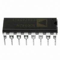
AD694JNZ
Description
IC TRANSMITTER 4-20MA 16-DIP
Manufacturer
Analog Devices Inc
Type
Current Transmitterr
Datasheet
1.AD694JNZ.pdf
(16 pages)
Specifications of AD694JNZ
Input Type
Voltage
Output Type
Voltage
Current - Supply
23mA
Mounting Type
Through Hole
Package / Case
16-DIP (0.300", 7.62mm)
Number Of Channels
1
Number Of Elements
3
Power Supply Requirement
Single
Common Mode Rejection Ratio
80dB
Voltage Gain Db
93.98dB
Input Resistance
5@24VMohm
Input Offset Voltage
0.5@24VmV
Input Bias Current
0.005@24V@-40C TO 85nA
Single Supply Voltage (typ)
5/9/12/15/18/24/28V
Dual Supply Voltage (typ)
Not RequiredV
Power Supply Rejection Ratio
80dB
Rail/rail I/o Type
No
Single Supply Voltage (min)
4.5V
Single Supply Voltage (max)
36V
Dual Supply Voltage (min)
Not RequiredV
Dual Supply Voltage (max)
Not RequiredV
Operating Temp Range
0C to 70C
Operating Temperature Classification
Commercial
Mounting
Through Hole
Pin Count
16
Package Type
PDIP
No. Of Amplifiers
4
Bandwidth
300kHz
Amplifier Output
Differential
Cmrr
90dB
Supply Voltage Range
4.5V To 36V, 12.5V To 36V
Supply Current
2mA
Rohs Compliant
Yes
Lead Free Status / RoHS Status
Lead free / RoHS Compliant
Interface
-
Lead Free Status / Rohs Status
RoHS Compliant part
Electrostatic Device
Available stocks
Company
Part Number
Manufacturer
Quantity
Price
Company:

Part Number:
AD694JNZ
Manufacturer:
ALTERA
Quantity:
3 000
Part Number:
AD694JNZ
Manufacturer:
ADI/亚德诺
Quantity:
20 000


AD694
Figure 6 will give an approximately linear adjustment of the
4 mA offset within fixed limits. To find the proper resistor val-
ues, first select X, the desired range of adjustment as a fraction
of 4 mA. Substitute this value in the appropriate formula below
along with the chosen reference output voltage (V
10 V usually), to determine the resistor values required.
R
R
These formulae take into account the ± 10% internal resistor
tolerance and ensure a minimum adjustment range for the 4 mA
offset. For example, assume the 2 V reference option has been
selected. Choosing X = 0.05, gives an adjustment range of ± 5%
of the 4 mA offset.
R
R
These can be rounded down to more convenient values of
2.5 kΩ and 9.76 kΩ. In general, if the value of R
down slightly, the value of R
tionately, and vice versa. This helps to keep the adjustment
range symmetrical.
ADJUSTING SPAN FOR 10 V FS
When the AD694 is configured with a 10 V input full-scale the
span maybe adjusted using the network shown in Figure 7. This
scheme allows an approximately linear adjustment of the span
above or below the nominal value. The span adjustment does
not interact with the 4 mA offset. To select R
P
F
P
F
= 180 Ω (1/X – 4.5)
= 500 Ω [(V
= 180 Ω (1/0.05 – 4.5) = 2.79 k Ω
= 500 Ω [(2 V / 1.22) – 0.18 – 0.82 × 0.05][1/0.05 – 4.5]
= 10.99 k Ω
Figure 6. Optional 4 mA Zero Adjustment
REF
/ 1.22 V) – 0.18 – 0.82X][1/X – 4.5]
F
should be rounded down propor-
S
and R
P
REF
is rounded
T
= 2 V or
, choose
–8–
X, the desired adjustment range as a fraction of the span. Sub-
stitute this value in the appropriate formula below.
These formulae take into account the ± 10% absolute resistor
tolerance of the internal span resistors and ensure a minimum
adjustment range of the span. For example, choosing the adjust-
ment range to be ± 2%, or 0.02 gives:
R
R
These values can be rounded up to the more convenient values
of 100 kΩ and 198 kΩ. In general, if R
value of R
ADJUSTING SPAN FOR 2 V FS
The precalibrated 2 V full-scale range requires a different ad-
justment scheme due to the single supply nature of the AD694.
Figure 8 shows an adjustment scheme that allows an approxi-
mately linear adjustment of the 2 V span plus or minus the
nominal value. The span adjustment does not affect the value of
the 4 mA offset current.
To find the proper resistor values first select X, the desired
range of adjustment as a fraction of the output span. Substitute
this value into the following formulae:
These formulae take into account the ± 10% absolute tolerance
of the internal span resistors and ensure a minimum adjustment
range.
For example, choosing the adjustment range to be ± 320 µA of
FS or, ± 2%, let X = 0.02. Thus:
Setting R
R
The value of R
49.9 Ω. In general, if R
rounded up proportionally, and vice versa; rounding up will in-
crease the range of adjustment.
T
S
C
= 1.8 k Ω ((1 – 0.02) / 0.02) = 88.2 k Ω .
= 9 k Ω [1 – 0.2 (1 + 0.02)( 1 – 0.02 )] / (2 × 0.02) =
= (2.75 kΩ × 0.02)/ (1 – 0.275 × (0.02)) = 55.3 Ω
Figure 7. Span Adjustment, 10 V Full Scale
R
R
R
R
B
S
T
S
A
C
= 10 K, then R
should be rounded up proportionally, and vice versa.
= 9 k Ω [1 – 0.2 (1 + X)( 1 – X )] / 2X
= 1.8 k Ω ((1 – X)/X)
= 2 × X × R
= (2.75 kΩ × X)/(1 – 0.275X)
C
can be rounded to the more convenient value of
A
B
is rounded up, then R
where R
A
175.5 k Ω
= 2(.02) × 10 kΩ = 400 Ω
B
is greater than 5 K
T
is rounded up, then the
C
should be
REV. B
Related parts for AD694JNZ
Image
Part Number
Description
Manufacturer
Datasheet
Request
R

Part Number:
Description:
±1.7g Dual-Axis IMEMS Accelerometer Evaluation Board
Manufacturer:
Analog Devices Inc
Datasheet:

Part Number:
Description:
Inertial Sensor Evaluation System
Manufacturer:
Analog Devices Inc
Datasheet:
Part Number:
Description:
Manufacturer:
Analog Devices Inc
Datasheet:
Part Number:
Description:
Manufacturer:
Analog Devices Inc
Datasheet:
Part Number:
Description:
Manufacturer:
Analog Devices Inc
Datasheet:
Part Number:
Description:
Manufacturer:
Analog Devices Inc
Datasheet:
Part Number:
Description:
Manufacturer:
Analog Devices Inc
Datasheet:
Part Number:
Description:
Manufacturer:
Analog Devices Inc
Datasheet:
Part Number:
Description:
Manufacturer:
Analog Devices Inc
Datasheet:
Part Number:
Description:
Manufacturer:
Analog Devices Inc
Datasheet:
Part Number:
Description:
Manufacturer:
Analog Devices Inc
Datasheet:
Part Number:
Description:
Manufacturer:
Analog Devices Inc
Datasheet:
Part Number:
Description:
Manufacturer:
Analog Devices Inc
Datasheet: