AD694JNZ Analog Devices Inc, AD694JNZ Datasheet - Page 9
AD694JNZ
Manufacturer Part Number
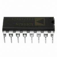
AD694JNZ
Description
IC TRANSMITTER 4-20MA 16-DIP
Manufacturer
Analog Devices Inc
Type
Current Transmitterr
Datasheet
1.AD694JNZ.pdf
(16 pages)
Specifications of AD694JNZ
Input Type
Voltage
Output Type
Voltage
Current - Supply
23mA
Mounting Type
Through Hole
Package / Case
16-DIP (0.300", 7.62mm)
Number Of Channels
1
Number Of Elements
3
Power Supply Requirement
Single
Common Mode Rejection Ratio
80dB
Voltage Gain Db
93.98dB
Input Resistance
5@24VMohm
Input Offset Voltage
0.5@24VmV
Input Bias Current
0.005@24V@-40C TO 85nA
Single Supply Voltage (typ)
5/9/12/15/18/24/28V
Dual Supply Voltage (typ)
Not RequiredV
Power Supply Rejection Ratio
80dB
Rail/rail I/o Type
No
Single Supply Voltage (min)
4.5V
Single Supply Voltage (max)
36V
Dual Supply Voltage (min)
Not RequiredV
Dual Supply Voltage (max)
Not RequiredV
Operating Temp Range
0C to 70C
Operating Temperature Classification
Commercial
Mounting
Through Hole
Pin Count
16
Package Type
PDIP
No. Of Amplifiers
4
Bandwidth
300kHz
Amplifier Output
Differential
Cmrr
90dB
Supply Voltage Range
4.5V To 36V, 12.5V To 36V
Supply Current
2mA
Rohs Compliant
Yes
Lead Free Status / RoHS Status
Lead free / RoHS Compliant
Interface
-
Lead Free Status / Rohs Status
RoHS Compliant part
Electrostatic Device
Available stocks
Company
Part Number
Manufacturer
Quantity
Price
Company:

Part Number:
AD694JNZ
Manufacturer:
ALTERA
Quantity:
3 000
Part Number:
AD694JNZ
Manufacturer:
ADI/亚德诺
Quantity:
20 000


PROGRAMMING OTHER SPANS
There are two methods for programming input spans less than
10 V. The first decreases the input span by programming a non-
inverting gain into the buffer amplifier. For example, to achieve
an input span of 0–5 V, the AD694 is set in its 10 V full-scale
mode and the buffer amplifier is configured with a noninverting
gain of 2 by adding 2 resistors. Now a 5 V signal at +Sig results
in a 10 V full-scale signal at FB (Pin 1), the input to the V/I.
This method requires that the V/I be programmed to a 10 V full
scale for input spans between 2 V to 10 V. It should be pro-
grammed to a 2 V full scale if input spans of less than 2 V are
required. This adjustment scheme makes the accuracy of the
span adjustment dependent upon the ratio accuracy of the re-
quired gain resistors. Thus, it is possible to accurately configure
spans other than 2 V or 10 V without using trimming potenti-
ometers, given that the resistor ratios are sufficiently accurate. A
supply voltage of 12.5 V is required for spans between 2 V and
10 V. Spans below 2 V require a V
A second method, allows other spans of less than 10 V to be
programmed when supply voltage is less than 12.5 V. Since the
AD694 amplifiers require 2.5 V of headroom for operation, a
5 V full-scale input is possible with a 7.5 V supply. This is
achieved by placing a resistor, in parallel with R2, (2 V FS [Pin
4] to Com [Pin 5]), to adjust the transconductance of the V/I
converter without a headroom penalty. A disadvantage of this
method is that the external resistor must match the internal re-
sistor in a precise manner, thus a span trim will be required.
The value should be chosen to allow for the ± 10% uncertainty
in the absolute value of the internal resistor R2.
ADJUSTING REFERENCE OUTPUT
Figure 9 shows one method of making small adjustments to the
10 V reference output. This circuit allows a linear adjustment
range of ± 200 mV. The 2 V reference may also be adjusted but
only in the positive direction.
Other reference voltages can be programmed by adding external
resistors. For example, a resistor placed in parallel with R5 can
be added to boost the reference output as high as 20 V. Con-
versely, a resistor in parallel with R6 can be used to set the refer-
ence voltage to a value between 2 V and 10 V. The output
voltage V
REV. B
Figure 8. Span Adjustment, 2 V Full Scale
REF
= 2 V (R6 + R5)/R5. In choosing external
S
of 4.5 V or greater.
–9–
adjustment resistors remember that the internal resistors, while
ratio matched to a high degree of accuracy, have an absolute re-
sistor tolerance of only ± 10%. Be prepared to compensate for
this if a precise voltage other than the precalibrated values of 2
V or 10 V is required.
BANDWIDTH CONTROL
The bandwidth of the AD694 can be limited to provide noise
filtering. This is achieved by connecting an external capacitor
from BW ADJ (Pin 14) to V
To program the bandwidth, substitute the desired bandwidth in
Hz, into the formula below to determine the required capacitor.
The bandwidth chosen will vary ± 10% due to internal resistor
tolerance, plus an additional amount due to capacitor tolerance.
This method of bandwidth control is not recommended as a
way to filter large high frequency transients in the input signal.
It is recommended that frequencies greater than the BW of the
buffer amplifier be eliminated with an input filter to avoid recti-
fication of noise by the input amplifiers.
BUFFER AMPLIFIER OFFSET ADJUST
The buffer amplifier input voltage offset has been laser trimmed
to a high degree of accuracy; however, there may be occasions
when an offset trim is desired. Figure 11 shows the adjustment
method; a trim range of greater than ± 2.5 mV is available with
this scheme. It is not recommended that this adjustment
method be used to affect the 4 mA offset current as the trim will
induce offset drift into the buffer amplifier. The buffer amplifier
will drift approximately 1 µV/°C for each 300 µV of induced
offset. To adjust the 4 mA offset current refer to the Adjusting
4 mA Zero section.
Figure 10. Noise Filtering with an External Capacitor
Figure 9. 10 V Reference Output Adjustment
C
=
1 2
/ (
π
S
×
(Pin 13) as shown in Figure 10.
BW
×
900
Ω
)
AD694
Related parts for AD694JNZ
Image
Part Number
Description
Manufacturer
Datasheet
Request
R

Part Number:
Description:
±1.7g Dual-Axis IMEMS Accelerometer Evaluation Board
Manufacturer:
Analog Devices Inc
Datasheet:

Part Number:
Description:
Inertial Sensor Evaluation System
Manufacturer:
Analog Devices Inc
Datasheet:
Part Number:
Description:
Manufacturer:
Analog Devices Inc
Datasheet:
Part Number:
Description:
Manufacturer:
Analog Devices Inc
Datasheet:
Part Number:
Description:
Manufacturer:
Analog Devices Inc
Datasheet:
Part Number:
Description:
Manufacturer:
Analog Devices Inc
Datasheet:
Part Number:
Description:
Manufacturer:
Analog Devices Inc
Datasheet:
Part Number:
Description:
Manufacturer:
Analog Devices Inc
Datasheet:
Part Number:
Description:
Manufacturer:
Analog Devices Inc
Datasheet:
Part Number:
Description:
Manufacturer:
Analog Devices Inc
Datasheet:
Part Number:
Description:
Manufacturer:
Analog Devices Inc
Datasheet:
Part Number:
Description:
Manufacturer:
Analog Devices Inc
Datasheet:
Part Number:
Description:
Manufacturer:
Analog Devices Inc
Datasheet: