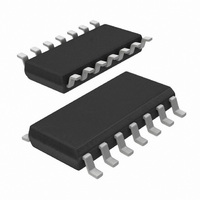
74LV4066D,112 NXP Semiconductors, 74LV4066D,112 Datasheet - Page 11

74LV4066D,112
Manufacturer Part Number
74LV4066D,112
Description
IC SWITCH QUAD 1X2 14SOIC
Manufacturer
NXP Semiconductors
Series
74LVr
Type
Analog Switchr
Datasheet
1.74LV4066DB112.pdf
(23 pages)
Specifications of 74LV4066D,112
Function
Switch
Circuit
4 x 1:2
Voltage Supply Source
Dual Supply
Voltage - Supply, Single/dual (±)
±1 V ~ 6 V
Current - Supply
40µA
Operating Temperature
-40°C ~ 125°C
Mounting Type
Surface Mount
Package / Case
14-SOIC (0.154", 3.90mm Width)
Package
14SO
Maximum On Resistance
130@2V Ohm
Maximum Propagation Delay Bus To Bus
8(Typ)@1.2V|5(Typ)@2V|3(Typ)@3.6V|2@4.5V|2(Typ)|(Typ)|(Typ)|(Typ)@6V ns
Maximum Low Level Output Current
25 mA
Maximum Turn-off Time
50(Typ)@1.2V ns
Maximum Turn-on Time
40(Typ)@1.2V ns
Switch Architecture
SPST
Power Supply Type
Single
Lead Free Status / RoHS Status
Lead free / RoHS Compliant
Other names
568-4600-5
74LV4066D
74LV4066D
935088370112
74LV4066D
74LV4066D
935088370112
Philips Semiconductors
9397 750 15209
Product data sheet
Table 9:
Voltages are referenced to GND (ground = 0 V); for test circuit see
[1]
[2]
[3]
Symbol Parameter
t
t
PHZ
PLZ
,
Typical values are measured at nominal V
C
P
f
f
C
C
V
N = number of inputs switching;
The condition is V
i
o
[(C
D
CC
PD
= input frequency in MHz;
L
S
= output frequency in MHz;
= output load capacitance in pF;
= C
= maximum switch capacitance in pF;
L
is used to determine the dynamic power dissipation (P
= supply voltage in V;
+ C
turn-off time nE to V
PD
Dynamic characteristics
S
)
V
CC
V
CC
2
2
I
= GND to V
f
i
f
o
N + [(C
] = sum of the outputs.
Rev. 03 — 4 July 2005
os
CC
L
+ C
.
S
)
…continued
Conditions
see
V
CC
CC
V
V
V
V
2
CC
CC
CC
CC
and T
Figure 9
f
= 2.0 V
= 2.7 V to 3.6 V
= 4.5 V
= 6.0 V
o
] where:
amb
= 25 C.
D
in W).
© Koninklijke Philips Electronics N.V. 2005. All rights reserved.
Figure
Quad bilateral switches
11.
Min Typ Max Unit
-
-
-
-
74LV4066
-
-
-
-
81
47
40
34
11 of 23
ns
ns
ns
ns


