M50FW040K1 STMicroelectronics, M50FW040K1 Datasheet - Page 12
M50FW040K1
Manufacturer Part Number
M50FW040K1
Description
Flash 3.6V 4M (512Kx8)
Manufacturer
STMicroelectronics
Datasheet
1.M50FW040K1.pdf
(41 pages)
Specifications of M50FW040K1
Data Bus Width
8 bit
Memory Type
NOR
Memory Size
4 Mbit
Architecture
Sectored
Interface Type
Firmware Hub
Access Time
11 ns, 50 ns
Supply Voltage (max)
3.6 V
Supply Voltage (min)
3 V
Maximum Operating Current
20 mA
Operating Temperature
+ 70 C
Mounting Style
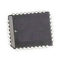
SMD/SMT
Package / Case
PLCC-32
Organization
512 KB x 8
Lead Free Status / Rohs Status
No
Available stocks
Company
Part Number
Manufacturer
Quantity
Price
Company:

Part Number:
M50FW040K1
Manufacturer:
ST
Quantity:
3 112
Company:
Part Number:
M50FW040K1
Manufacturer:
STM
Quantity:
245
Company:
Part Number:
M50FW040K1
Manufacturer:
QP-SEMI
Quantity:
13
Part Number:
M50FW040K1
Manufacturer:
ST
Quantity:
20 000
Company:
Part Number:
M50FW040K1T
Manufacturer:
TI
Quantity:
125
Part Number:
M50FW040K1T
Manufacturer:
ST
Quantity:
20 000


M50FW040
subset of the features available to the Firmware
Hub (FWH) Interface are available; these include
all the Commands but exclude the Security fea-
tures and other registers.
The following operations can be performed using
the appropriate bus cycles: Bus Read, Bus Write,
Output Disable and Reset.
When the Address/Address Multiplexed (A/A Mux)
Interface is selected all the blocks are unprotect-
ed. It is not possible to protect any blocks through
this interface.
Bus Read. Bus Read operations are used to out-
put the contents of the Memory Array, the Elec-
tronic Signature and the Status Register. A valid
Bus Read operation begins by latching the Row
Address and Column Address signals into the
memory using the Address Inputs, A0-A10, and
the Row/Column Address Select RC. Then Write
Enable (W) and Interface Reset (RP) must be
High, V
to perform a Bus Read operation. The Data Inputs/
Outputs will output the value, see
Mux Interface Read AC
22., A/A Mux Interface Read AC
for details of when the output becomes valid.
Table 4. FWH Bus Read Field Definitions
12/41
Number
Clock
Cycle
13-14
16-17
3-9
10
12
15
18
19
11
1
2
IH
, and Output Enable, G, Low, V
Count
Clock
Cycle
1
1
7
1
1
1
2
1
2
1
1
WSYNC
RSYNC
START
MSIZE
IDSEL
ADDR
DATA
Field
TAR
TAR
TAR
TAR
Waveforms, and
FWH0-
FWH3
1101b
0000b
0101b
0000b
XXXX
XXXX
XXXX
1111b
1111b
(float)
1111b
1111b
(float)
Characteristics,
Figure 14., A/A
Memory
N/A
I/O
O
O
O
O
O
I
I
I
I
I
IL
, in order
On the rising edge of CLK with FWH4 Low, the contents of FWH0-
FWH3 indicate the start of a FWH Read cycle.
Indicates which FWH Flash Memory is selected. The value on FWH0-
FWH3 is compared to the IDSEL strapping on the FWH Flash
Memory pins to select which FWH Flash Memory is being addressed.
A 28-bit address phase is transferred starting with the most significant
nibble first.
Always 0000b (only single byte transfers are supported).
The host drives FWH0-FWH3 to 1111b to indicate a turnaround cycle.
The FWH Flash Memory takes control of FWH0-FWH3 during this
cycle.
The FWH Flash Memory drives FWH0-FWH3 to 0101b (short wait-
sync) for two clock cycles, indicating that the data is not yet available.
Two wait-states are always included.
The FWH Flash Memory drives FWH0-FWH3 to 0000b, indicating
that data will be available during the next clock cycle.
Data transfer is two CLK cycles, starting with the least significant
nibble.
The FWH Flash Memory drives FWH0-FWH3 to 1111b to indicate a
turnaround cycle.
The FWH Flash Memory floats its outputs, the host takes control of
FWH0-FWH3.
Table
Bus Write. Bus Write operations write to the
Command Interface. A valid Bus Write operation
begins by latching the Row Address and Column
Address signals into the memory using the Ad-
dress Inputs, A0-A10, and the Row/Column Ad-
dress Select RC. The data should be set up on the
Data Inputs/Outputs; Output Enable, G, and Inter-
face Reset, RP, must be High, V
able, W, must be Low, V
Outputs are latched on the rising edge of Write En-
able, W. See
AC
Write AC
requirements.
Output Disable. The data outputs are high-im-
pedance when the Output Enable, G, is at V
Reset. During Reset mode all internal circuits are
switched off, the memory is deselected and the
outputs are put in high-impedance. The memory is
in Reset mode when RP is Low, V
held Low, V
ing a Program or Erase operation, the operation is
aborted and the memory cells affected no longer
contain valid data; the memory can take up to t
RH
to abort a Program or Erase operation.
Waveforms, and
Characteristics, for details of the timing
IL
for t
Description
Figure 15., A/A Mux Interface Write
PLPH
Table 23., A/A Mux Interface
. If RP is goes Low, V
IL
. The Data Inputs/
IH
IL
and Write En-
. RP must be
IL
IH
, dur-
.
PL-
Related parts for M50FW040K1
Image
Part Number
Description
Manufacturer
Datasheet
Request
R

Part Number:
Description:
Fast Recovery High Voltage Silicon Diodes
Manufacturer:
Voltage Multipliers, Inc.

Part Number:
Description:
STMicroelectronics [RIPPLE-CARRY BINARY COUNTER/DIVIDERS]
Manufacturer:
STMicroelectronics
Datasheet:
Part Number:
Description:
STMicroelectronics [LIQUID-CRYSTAL DISPLAY DRIVERS]
Manufacturer:
STMicroelectronics
Datasheet:

Part Number:
Description:
BOARD EVAL FOR MEMS SENSORS
Manufacturer:
STMicroelectronics
Datasheet:
Part Number:
Description:
NPN TRANSISTOR POWER MODULE
Manufacturer:
STMicroelectronics
Datasheet:
Part Number:
Description:
TURBOSWITCH ULTRA-FAST HIGH VOLTAGE DIODE
Manufacturer:
STMicroelectronics
Datasheet:
Part Number:
Description:
Manufacturer:
STMicroelectronics
Datasheet:
Part Number:
Description:
DIODE / SCR MODULE
Manufacturer:
STMicroelectronics
Datasheet:
Part Number:
Description:
DIODE / SCR MODULE
Manufacturer:
STMicroelectronics
Datasheet:
Part Number:
Description:
Search -----> STE16N100
Manufacturer:
STMicroelectronics
Datasheet:
Part Number:
Description:
Search ---> STE53NA50
Manufacturer:
STMicroelectronics
Datasheet:
Part Number:
Description:
NPN Transistor Power Module
Manufacturer:
STMicroelectronics
Datasheet: