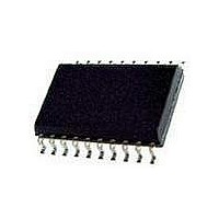
PCA9559PW NXP Semiconductors, PCA9559PW Datasheet - Page 7

PCA9559PW
Manufacturer Part Number
PCA9559PW
Description
EEPROM 5BIT MUX/1BIT LATCH 6-BIT DIPSW
Manufacturer
NXP Semiconductors
Datasheet
1.PCA9559PW.pdf
(11 pages)
Specifications of PCA9559PW
Interface Type
I2C
Maximum Clock Frequency
400 KHz
Access Time
10 ns
Supply Voltage (max)
3.6 V
Supply Voltage (min)
3 V
Maximum Operating Current
100 uA
Maximum Operating Temperature
+ 70 C
Mounting Style
SMD/SMT
Package / Case
SOT-360
Minimum Operating Temperature
0 C
Operating Supply Voltage
3 V to 3.6 V
Operating Temperature
0 C to + 70 C
Lead Free Status / Rohs Status
Details
Other names
PCA9559PW,112
Available stocks
Company
Part Number
Manufacturer
Quantity
Price
Part Number:
PCA9559PW
Manufacturer:
PHILIPS/飞利浦
Quantity:
20 000
Company:
Part Number:
PCA9559PWЈ¬118
Manufacturer:
NXP
Quantity:
30
Philips Semiconductors
AC CHARACTERISTICS
NOTE:
1. WRITE CYCLE time can only be measured indirectly during the write cycle. During this time, the device will not acknowledge its I
2003 Jun 27
MUX_IN ⇒ MUX_OUT
Select ⇒ MUX_OUT
OVERRIDE_N ⇒ NON-MUXED_OUT
OVERRIDE_N ⇒ MUX_OUT
I
2
5-bit multiplexed/1-bit latched 6-bit
I
C-bus
2
SYMBOL
t
t
C EEPROM DIP switch
t
t
t
HD:STA
SU:STA
HD:DAT
SU:DAT
SU:STO
t
t
t
t
t
t
t
t
t
t
tPLH
tPHL
HIGH
LOW
t
T
PLH
PHL
PLH
PHL
PLH
PHL
SCL
BUF
P
C
C
t
t
SP
t
t
R
R
F
W
F
I
L
L
LOW-to-HIGH transition time
HIGH-to-LOW transition time
LOW-to-HIGH transition time
HIGH-to-LOW transition time
LOW-to-HIGH transition time
HIGH-to-LOW transition time
LOW-to-HIGH transition time
HIGH-to-LOW transition time
Output rise time
Output fall time
Pull-up resistor for outputs
Test load capacitance on outputs
SCL clock frequency
Bus free time between a STOP and a START condition
Hold time (repeated) START condition. After this period, the first
clock pulse is generated
LOW period of SCL clock
HIGH period of SCL clock
Set-up time for a repeated START condition
Data hold time
Data set-up time
Data spike time
Set-up time for STOP condition
Rise time for both SDA and SCL signals (10 - 400 pF bus)
Fall time for both SDA and SCL signals (10 - 400 pF bus)
Capacitive load for each bus line
Write cycle time
1
PARAMETER
7
MIN.
600
600
600
100
600
1.0
1.0
1.0
1.3
1.3
10
20
20
—
—
—
—
—
—
—
—
—
—
—
0
0
LIMITS
TYP.
28
16
30
17
34
19
31
21
15
—
—
—
—
—
—
—
—
—
—
—
—
—
—
—
—
—
MAX.
-100
400
-12
-32
300
300
400
37
21
39
22
43
25
41
27
10
50
10
—
—
—
—
—
—
3
3
PCA9559
2
Product data
C Address.
UNIT
ns/V
ns/V
ns/V
kHz
ms
ns
ns
ns
ns
ns
ns
ns
ns
pF
µs
ns
µs
ns
ns
ns
ns
ns
ns
ns
ns
pF


