F10-S30R Omron, F10-S30R Datasheet
F10-S30R
Specifications of F10-S30R


Related parts for F10-S30R

F10-S30R Summary of contents
Page 1
... RS-422 (cable length F10-VR4 8 Setting distance 100± ´ 50± ´ 33±3 mm 4.5 ´ 3.5 mm Output No. of registered models (one model per bank) 8 (one model per bank) Model F10 Detection range Model F10-S30R F10-S15R F10-S05R Model F10-C20 F10-C25 F10-C30 F10-C35 F10-C50 F10-C55 ...
Page 2
... LEDs (540 nm) Black and white, red and white, green and white, blue and white, green and black, and blue and black 1 blue LED (470 nm) Specifications F10-S30R F10-S15R Specification 0°C to 40°C (with no icing or condensation) - -25°C to 60°C (with no icing or condensation) ...
Page 3
... Short-circuited with Input is ON: short-circuit current max. or 1.5 V max. Input is OFF: Open or input voltage max. (Max. input voltage: +26.4 VDC) F10-S30R, F10-S15R, or F10-S05R 1 orange LED 8 green LEDs 7 red LEDs 3 on the C20/C25 the C30/C35/C50/C55 Specification 0°C to 50°C (with no icing or condensation) - -25° ...
Page 4
... F10 Engineering Data Data Characteristics F10-S30R Rotation Shift angle Rotation Characteristics Angle of rotation (W.D. 100 mm) Distance Characteristics W. D. (mm) F10-S15R Rotation Shift angle Rotation Characteristics Angle of rotation (W.D. 50 mm) Distance Characteristics W. D. (mm) · The following data is obtained on the basis of sample sensing objects, each of which is as large as this size (A). (Typical example) · ...
Page 5
... F10 12 F10-S05R available soon F10 ...
Page 6
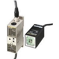
... F10 Nomenclature Heads F10-S30R Guide light (green) F10-S30R with 2-m standard cable Object lighting (red) F10-S15R Guide light (blue) Object lighting (green) F10-S15R with 2-m standard cable F10-S05R Guide light (blue) Object lighting (green) 33±3 mm F10-S05R with 2-m standard cable 100±10 mm ...
Page 7
... Degree of conformity model d: Plain measurement: Deviation level a: Plain measurement: Difference from average density Also displays bank number for F10-C30/C35/C50/C55 (5) Starts teaching. Switches display item. (6) Changes the threshold value. Changes measurement item selection level for plain measure- ment. Changes bank number for F10-C30/C35/C50/C55. ...
Page 8
... No Marking: Timer OFF. Matching/Not Matching Output ON when object does not match registered model. Output ON when object matches registered model. External Input (F10-C50/C55 only) LINE: Executes external input in RUN mode via input line. RS-232C/422: Executes external input in RUN mode via serial communications. A.T. ON ...
Page 9
... Mounting Angle · Incline the Head by 15° and mount the Head so that no regular reflection light affects the Sensor. · Use the provided Mounting Bracket to mount the Head. F10-S30R: 100±10 mm F10-S15R: 50±5 mm 15° F10-S05R: 33±3 mm Note: Position the sensor perpendicular to the direction of motion of the target object. ...
Page 10
... F10 Multidrop Connections A maximum of 31 F10-C50/C55 Sensors can communicate with an IBM PC/AT or compatible by connecting though RS-232C/422 converters. Recommended Link Adapters (manufactured by OMRON) Link Adapter: B500-AL004 Branching Link Adapter: B500-AL001 Note: When using a B500-AL004 Branching Link Adapter, be sure to enable terminating resistance and include a terminating resistance in the last link adapter according to the following: Between RDA(- -) and RDB(+): 220 W (1/2 W min ...
Page 11
... All input signals are enabled in RUN mode only. 18 F10-C25 PNP Models There are gray, green, and red input lines, but they are not used with this model. Take steps to ensure that these lines will not be short-cir- cuited with other lines. ...
Page 12
... Set the mode selector to TEACH. (2) Make the automatic teaching and model size settings on the DIP switch. If using an F10-C30/C35/C50/C55 step (3) to set the bank number. If using an F10-C20/C25 step (5). (3) Set the measurement item/bank number selection switch to PATT/BANK. Bank No. 0 will be displayed. (4) Press the UP/DOWN select buttons to set the bank number. ...
Page 13
... Plain Measurement High Deviation Approx. 3 (F10-S30R) Low Approx. 1.5 mm (F10-S15R) Measurement item Approx. 0.8 mm selection level (F10-S05R) Teaching is performed in the area enclosed by dotted lines inside the sensing area. The pattern close to the edge of the sensing area is not registered as a model because such a ...
Page 14
... F10 Plain Measurement Press the teach/display button to change the display (DEV-AVE). · Status indicators (F10-C20/C25) Plain measurement · Status indicator (F10-C30/C35/C50/C55) Press the teach/ display button Displays the mode indicating the current level. Bank No. (2) Press the UP/DOWN selection buttons to adjust the threshold. ...
Page 15
... Performing Measurement in Response to External Input Signals (RUN Mode) (1) Set the mode selector to RUN. When the switch is set to RUN mode, measurements are made in response to external input signals. Relationship between the F10 I/O terminal operations and ON/OFF indications in the timing charts are as shown in the following table. Signal Input ...
Page 16
... The bank is being switched. 6. The guide light is being turned ON or OFF. RS-232C/422 Command Inputs (F10-C50/C55 Only) Communications with external devices, such as an IBM PC/AT or compatible, is possible via the RS-232/422 port. Refer to the Operation Manual for the unit for details on the communications commands. ...
Page 17
... All internal data of the Amplifier may be cleared. Note: If the same error occurs again after turning the Sensor OFF and ON, consult your OMRON representa- tive. Connect an F10-S30R/S15R/S05R to the head. Perform the teaching of the Sensor in TEACH mode. Refer to 1. Pattern Registration (TEACH Mode) on page 19. ...
Page 18
... F10 Remedy Send buffer overflow Change the communications settings. Receive buffer overflow Wait for a response from the F10, then send the command. Reduce the current so that it will not exceed the rated value. Note: If the output does not turn ON even after reducing the current below the rated value, contact your OMRON representative ...
Page 19
... F10 Heads F10-SjR 14.7-dia. connector (125) 5.8-dia. Vinyl-insulated round cable, standard length Mounting Bracket 26 The Mounting Bracket can be attached to this side as well. Ferrite core (75) Mounting hole 2-M4 pan-head screw Mounting Dimensions Two, M4 37±0.2 Protruding part F10 Mounting hole (16.7) R1 max. ...
Page 20
... Amplifiers Do not disconnect or connect the Head while the Sensor is turned ON. The F10-S30R cannot detect red objects with white backgrounds. Use the F10-S15R instead. The F10-S15R cannot detect green objects with white back- grounds. Use the F10-S30R instead. Make sure that the length of the cable of the Amplifier is no longer than 20 m ...
Page 21
... Clemenceau Avenue, #11-01, UE Square, Singapore 239920 Tel: (65)835-3011/Fax: (65)835-2711 OMRON (CHINA) CO. LTD. 21F, Beijing East Ocean Center No. 24A Jian Guo Men Wai Da Jie Chao Yang District, Beijing, 100022 China Tel: (86)10-6515-5778/Fax: (86)10-6515-5810 28 Authorized Distributor: Cat. No. Q120-E1-1 F10 Printed in Japan 0100-10M (0100) ...