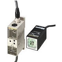
F10-S30R Omron, F10-S30R Datasheet - Page 11

F10-S30R
Manufacturer Part Number
F10-S30R
Description
25C4243
Manufacturer
Omron
Datasheet
1.F10-S30R.pdf
(21 pages)
Specifications of F10-S30R
Sensing Range
90mm To 110mm
Peak Reflow Compatible (260 C)
No
Terminal Type
Wire Leaded
Supply Current Max
150mA
Supply Voltage Max
19.8VDC
Sensor Terminals
Cable
Leaded Process Compatible
No
Rohs Compliant
No
F10
Operation
F10-C20 NPN Models
There are gray, green, and red input lines, but they are not used with
this model. Take steps to ensure that these lines will not be short-cir-
cuited with other lines.
F10-C30/C50 NPN Models
Note:
I/O Signals
·
18
Thresh-
old indi-
cators
red
LEDs)
OUTPUT
ENAB
S_TEACH
M_TEACH
TRIG
CONT
BANK1
BANK2
BANK3
Threshold
indicators
LEDs)
(7-level
(7-level red
I/O Circuit Diagram
All input signals are enabled in RUN mode only.
Level indi-
cators
(8-level
green
LEDs)
Level in-
dicators
(8-level
green
LEDs)
Result
indicator
(1-level
orange
LED)
Result in-
dicator
(1-level
orange
LED)
Status
indica-
tors
(3-level
green
LEDs)
Status
indica-
tors
(3-level
green
LEDs)
Bank
No. in-
dica-
tors
(7-lev-
el red
LEDs)
Signal
For normal operation, ground or connect the shielded cable to 0 V. The shield is not connected to the interior or casing.
Amplifi-
er main
circuit
Amplifi-
er main
circuit
Black
Orange
Yellow
Purple
Pink
White
Gray
Green
Red
Blue
(GND)
Purple
Black
Orange
Yellow
White
Brown (Vcc)
Pink
Blue
(GND)
Brown (Vcc)
Control output
Enabled output
Stationary object teaching input
Moving object teaching input
Measurement trigger input
Continuous measurement input
Bank switching input
Bank switching input
(F10-C30/C35/C50/C55)
(F10-C30/C35/C50/C55)
Shield
Shield
Function
Load
Load
CONT
21.6 to 26.4 VDC
21.6 to 26.4 VDC
BANK1
FG (see note)
FG (see note)
BANK2
BANK3
Load
Load
Thresh-
old indi-
cators
red
LEDs)
(7-level
Threshold
indicators
LEDs)
(7-level red
F10-C25 PNP Models
There are gray, green, and red input lines, but they are not used with
this model. Take steps to ensure that these lines will not be short-cir-
cuited with other lines.
F10-C35/C55 PNP Models
Switching Banks (F10-C30/C35/C50/C55)
You can switch banks by connecting BANK1 to BANK3 as shown
below.
Bank 0
Bank 1
Bank 2
Bank 3
Bank 4
Bank 5
Bank 6
Bank 7
Result in-
dicator
(1-level
orange
LED)
Result in-
dicator
(1-level
orange
LED)
Level in-
dicators
(8-level
green
LEDs)
Level in-
dicators
(8-level
green
LEDs)
Bank No.
Status
indica-
tors
(3-level
green
LEDs)
Status
indica-
tors
(3-level
green
LEDs)
Bank
No. indi-
cators
(7-level
red
LEDs)
Amplifi-
er main
circuit
Amplifi-
er main
circuit
OFF
ON
OFF
ON
OFF
ON
OFF
ON
BANK1
Brown (Vcc)
Yellow
Purple
Pink
White
Black
Orange
Blue
(GND)
Brown (Vcc)
Yellow
Purple
Pink
White
Gray
Green
Red
Black
Orange
Blue
(GND)
ENAB
ENAB
OFF
OFF
ON
ON
OFF
OFF
ON
ON
Load
Load
Shield
BANK2
Shield
21.6 to 26.4 VDC
21.6 to 26.4 VDC
FG (see note)
OFF
OFF
OFF
OFF
ON
ON
ON
ON
Load
Load
FG (see note)
BANK3
F10


