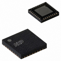
SC16C2550BIBS,151 NXP Semiconductors, SC16C2550BIBS,151 Datasheet - Page 39

SC16C2550BIBS,151
Manufacturer Part Number
SC16C2550BIBS,151
Description
IC UART DUAL W/FIFO 32-HVQFN
Manufacturer
NXP Semiconductors
Type
5 V, 3.3 V and 2.5 V dual UART, 5 Mbit/s with 16-byte FIFOsr
Datasheet
1.SC16C2550BIA44518.pdf
(43 pages)
Specifications of SC16C2550BIBS,151
Number Of Channels
2, DUART
Package / Case
32-VFQFN Exposed Pad
Features
False-start Bit Detection
Fifo's
16 Byte
Voltage - Supply
3.5 V ~ 4.5 V
With Auto Flow Control
Yes
With False Start Bit Detection
Yes
With Modem Control
Yes
With Cmos
Yes
Mounting Type
Surface Mount
Data Rate
5 Mbps
Supply Voltage (max)
5.5 V
Supply Voltage (min)
2.25 V
Supply Current
4.5 mA
Maximum Operating Temperature
+ 85 C
Minimum Operating Temperature
- 40 C
Mounting Style
SMD/SMT
Operating Supply Voltage
2.5 V or 3.3 V or 5 V
Lead Free Status / RoHS Status
Lead free / RoHS Compliant
Lead Free Status / RoHS Status
Lead free / RoHS Compliant, Lead free / RoHS Compliant
Other names
568-3259
935280309151
SC16C2550BIBS-S
935280309151
SC16C2550BIBS-S
Available stocks
Company
Part Number
Manufacturer
Quantity
Price
Company:
Part Number:
SC16C2550BIBS,151
Manufacturer:
NXP
Quantity:
1 861
NXP Semiconductors
13. Soldering of through-hole mount packages
SC16C2550B_5
Product data sheet
13.1 Introduction to soldering through-hole mount packages
13.2 Soldering by dipping or by solder wave
13.3 Manual soldering
For further information on temperature profiles, refer to Application Note AN10365
“Surface mount reflow soldering description” .
This text gives a very brief insight into wave, dip and manual soldering.
Wave soldering is the preferred method for mounting of through-hole mount IC packages
on a printed-circuit board.
Driven by legislation and environmental forces the worldwide use of lead-free solder
pastes is increasing. Typical dwell time of the leads in the wave ranges from
3 seconds to 4 seconds at 250 C or 265 C, depending on solder material applied, SnPb
or Pb-free respectively.
The total contact time of successive solder waves must not exceed 5 seconds.
The device may be mounted up to the seating plane, but the temperature of the plastic
body must not exceed the specified maximum storage temperature (T
printed-circuit board has been pre-heated, forced cooling may be necessary immediately
after soldering to keep the temperature within the permissible limit.
Apply the soldering iron (24 V or less) to the lead(s) of the package, either below the
seating plane or not more than 2 mm above it. If the temperature of the soldering iron bit is
less than 300 C it may remain in contact for up to 10 seconds. If the bit temperature is
between 300 C and 400 C, contact may be up to 5 seconds.
Fig 22. Temperature profiles for large and small components
temperature
MSL: Moisture Sensitivity Level
5 V, 3.3 V and 2.5 V dual UART, 5 Mbit/s (max.), with 16-byte FIFOs
Rev. 05 — 12 January 2009
= minimum soldering temperature
maximum peak temperature
minimum peak temperature
= MSL limit, damage level
SC16C2550B
temperature
peak
stg(max)
© NXP B.V. 2009. All rights reserved.
001aac844
). If the
time
39 of 43


