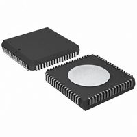
SC16C654BIA68,512 NXP Semiconductors, SC16C654BIA68,512 Datasheet - Page 21

SC16C654BIA68,512
Manufacturer Part Number
SC16C654BIA68,512
Description
ID QUAD UART 64BYTE 68PLCC
Manufacturer
NXP Semiconductors
Datasheet
1.SC16C654BIBS528.pdf
(58 pages)
Specifications of SC16C654BIA68,512
Features
False-start Bit Detection
Number Of Channels
4, QUART
Fifo's
64 Byte
Voltage - Supply
2.5V, 3.3V, 5V
With Auto Flow Control
Yes
With Irda Encoder/decoder
Yes
With False Start Bit Detection
Yes
With Modem Control
Yes
With Cmos
Yes
Mounting Type
Surface Mount
Package / Case
68-LCC (J-Lead)
Transmit Fifo
64Byte
Receive Fifo
64Byte
Transmitter And Receiver Fifo Counter
Yes
Data Rate
5Mbps
Package Type
PLCC
Operating Supply Voltage (max)
5.5V
Mounting
Surface Mount
Operating Temperature (min)
-40C
Operating Temperature (max)
85C
Operating Temperature Classification
Industrial
Lead Free Status / RoHS Status
Lead free / RoHS Compliant
Other names
935274935512
SC16C654BIA68
SC16C654BIA68
SC16C654BIA68
SC16C654BIA68
Available stocks
Company
Part Number
Manufacturer
Quantity
Price
Company:
Part Number:
SC16C654BIA68,512
Manufacturer:
NXP Semiconductors
Quantity:
10 000
Philips Semiconductors
9397 750 14965
Product data sheet
SC16C654B/654DB sets the default baud rate table according to the state of the CLKSEL
pin. A logic 1 on CLKSEL will set the 1 clock default, whereas logic 0 will set the 4 clock
default table. Following the default clock rate selection during initialization, the rate tables
can be changed by the internal register MCR[7]. Setting MCR[7] to a logic 1 when
CLKSEL is a logic 1 provides an additional divide-by-4, whereas setting MCR[7] to a
logic 0 only divides by 1; see
achieved by selecting the proper divisor values for the MSB and LSB sections of baud rate
generator.
Programming the Baud Rate Generator Registers DLM (MSB) and DLL (LSB) provides a
user capability for selecting the desired final baud rate. The example in
two selectable baud rate tables available when using a 7.3728 MHz crystal.
Table 7:
Output baud rate
MCR[7] = 1
50
300
600
1200
2400
4800
9600
19.2 k
38.4 k
57.6 k
115.2 k
Fig 11. Baud rate generator circuitry
XTAL1
XTAL2
Baud rate generator programming table using a 7.3728 MHz clock
MCR[7] = 0
200
1200
2400
4800
9600
19.2 k
38.4 k
76.8 k
153.6 k
230.4 k
460.8 k
OSCILLATOR
CLOCK
LOGIC
5 V, 3.3 V and 2.5 V quad UART, 5 Mbit/s (max.) with 64-byte FIFOs
Rev. 02 — 20 June 2005
User
16 clock divisor
Decimal
2304
384
192
96
48
24
12
6
3
2
1
Table 7
DIVIDE-BY-1
DIVIDE-BY-4
and
LOGIC
LOGIC
Figure
HEX
900
180
C0
60
30
18
0C
06
03
02
01
SC16C654B/654DB
11. Customized baud rates can be
MCR[7] = 0
MCR[7] = 1
DLM
program value
(HEX)
09
01
00
00
00
00
00
00
00
00
00
© Koninklijke Philips Electronics N.V. 2005. All rights reserved.
GENERATOR
BAUD RATE
LOGIC
Table 7
DLL
program value
(HEX)
00
80
C0
60
30
18
0C
06
03
02
01
002aaa208
BAUDOUT
shows the
21 of 58


