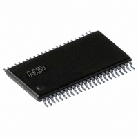
SC28L201A1DGG,112 NXP Semiconductors, SC28L201A1DGG,112 Datasheet - Page 19

SC28L201A1DGG,112
Manufacturer Part Number
SC28L201A1DGG,112
Description
IC UART W/FIFO 48-TSSOP
Manufacturer
NXP Semiconductors
Series
IMPACTr
Datasheet
1.SC28L201A1DGG118.pdf
(110 pages)
Specifications of SC28L201A1DGG,112
Features
False-start Bit Detection
Number Of Channels
2, DUART
Fifo's
256 Byte
Voltage - Supply
3.3V, 5V
With Parallel Port
Yes
With Auto Flow Control
Yes
With False Start Bit Detection
Yes
With Modem Control
Yes
With Cmos
Yes
Mounting Type
Surface Mount
Package / Case
48-TSSOP
Lead Free Status / RoHS Status
Lead free / RoHS Compliant
Other names
568-3293-5
935277824112
SC28L201A1DGG
935277824112
SC28L201A1DGG
Philips Semiconductors
9397 750 13138
Product data sheet
7.4.3 Transmission of ‘break’
7.4.4 1x and 16x modes, transmitter
7.4.5 Transmitter FIFO
7.4.6 Transmitter
transmitter enable/disable bit in the command register is at zero the TxFIFO will not
accept any more characters and the Tx Idle and TxRDY bits of the status register set to
zero.
Transmission of a break character is often needed as a synchronizing condition in a data
stream. The ‘break’ is defined as a start bit followed by all zero data bits by a zero parity
bit (if parity is enabled) and a zero in the stop bit position. The forgoing is the minimum
time to define a break. The transmitter can be forced to send a break (continuous LOW
condition) by issuing a start break command via the CR. Once the break starts, the TXD
output remains LOW until the host issues a command to ‘stop break’ via the CR or the
transmitter is issued a software or hardware reset. In normal operation the break is usually
much longer than one character time.
The transmitter clocking has two modes: 16 and 1 . Data is always sent at the 1 rate.
However. the logic of the transmitter may be operated with a clock that is 16 times faster
than the data rate or at the same rate as the data, that is, 1 . All clocks selected internally
for the transmitter (and the receiver) will be 16 clocks. Only when an external clock is
selected may the transmitter logic and state machine operate in the 1 mode. The 1 or
16 clocking makes little difference in transmitter operation. (This is not true in the
receiver.) In the 16 -clock mode, the transmitter will recognize a byte in the TxFIFO within
1
delay may be up to 2 bit times.
The FIFO configuration of the SC28L201 is as 256 8-bit words. Interrupt levels may be set
to any level within the FIFO size and may be set differently for each FIFO. Logic
associated with the FIFO encodes the number of empty positions for presentation to the
interrupt arbitration system. The encoding value is the number of empty positions. Thus,
an empty TxFIFO will bid with the value or 255; when full it will not bid at all; one position
empty bids with the value 0. A Full TxFIFO will not bid since no character is available.
Normally TxFIFO will present a bid to the arbitration system whenever it has one or more
empty positions. The bits of the TxFIFO Interrupt Level in MR0[5:4] allow the user to
modify this characteristic so that bidding will not start until one of four levels (one or more
filled, empty, 16 filled, 240 filled, full) have been reached. As will be shown later, this
feature may be used to make moderate improvements in the interrupt service efficiency. A
similar system exists for the Receiver.
The SC28L201 is conditioned to transmit data when the transmitter is enabled through the
Command Register. The transmitter of the SC28L201 indicates to the CPU that it is ready
to accept a character by setting the ISR TxRDY bit in the Status Register. This condition
can be programmed to generate an interrupt request at I/O4 or IRQN. When the
transmitter is initially enabled the TxRDY and Tx Idle bits will be set in the Status Register.
When a character is loaded to the transmit FIFO, the Tx Idle bit will be reset. The Tx Idle
bit will not set until the transmit FIFO is empty and the transmit shift register has finished
transmitting the stop bit of the last character written to the transmit FIFO.
16
-bit time to
2
16
-bit time and thus begin transmission of the start bit. In the 1 mode this
Rev. 01 — 31 October 2005
3.3 V, 5 V UART, 3.125 Mbit/s, with 256-byte FIFO
© Koninklijke Philips Electronics N.V. 2005. All rights reserved.
SC28L201
19 of 110


