ISD5008PY Nuvoton Technology Corporation of America, ISD5008PY Datasheet - Page 22
ISD5008PY
Manufacturer Part Number
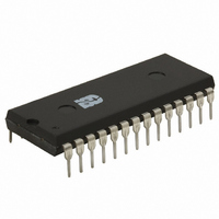
ISD5008PY
Description
IC VOICE REC/PLAY 4-8MIN 28-DIP
Manufacturer
Nuvoton Technology Corporation of America
Series
ISD5008r
Specifications of ISD5008PY
Interface
SPI/Microwire
Filter Pass Band
1.7 ~ 3.4kHz
Duration
4 ~ 8 Min
Mounting Type
Through Hole
Package / Case
28-DIP (0.600", 15.24mm)
For Use With
ISD-ES511 - EVALUATION SYSTEM FOR ISD5100ISD-ES501 - EVALUATION SYSTEM FOR ISD5008
Lead Free Status / RoHS Status
Lead free / RoHS Compliant
Available stocks
Company
Part Number
Manufacturer
Quantity
Price
Company:

Part Number:
ISD5008PY
Manufacturer:
Nuvoton
Quantity:
226


ISD5008 Product
Configuration Register Notes
1. Important: All changes to the internal settings of the ISD5008 are synchronized with the load of Configuration
2. Configuration Registers may be loaded with data at any time, including when the chip is powered down using
18
AGC Power Control
Bit
LOW PASS FILTER
Power Control Bit
SAMPLE RATE and
LOW PASS FILTER
Control Bits
FILTER MUX Control
bits
SUM 2 SUMMING AMP
Control Bits
SUM1 SUMMING AMP
Control Bits
SUM1MUX Control Bits
VOLUME CONTROL
Control Bits
VOL MUX Control Bits
Register 1. A command to load Configuration Register 1 immediately transfers the input data to the internal
settings of the device and the changes take place immediately at the end of the command when SS\ goes
HIGH. A load to Configuration Register 0 sends the new data to a temporary register in the ISD5008 and does
not affect the internal settings of the device. The next time Configuration Register 1 is loaded, data will also
transfer from the temporary register to the Configuration 0 Register and effect the desired changes. See Figure
Table 13.
the PU bit in the SPI Control Register. The PU bit in the SPI Control Word will have to be set to a “1” before the
changes in configuration will be seen.
Bit 10,9
Bit 15,14 (VLS1, VLS0)
Bit 0
(AGPD)
Bit 1
(FLPD)
Bits 3,2
(FLD1, FLD0)
Bit 4
(FLS0)
Bits 6,5
(S2M1, S2M0)
Bit 8,7
(S1M1, S1M0)
(S1S1, S1S0)
Bits 13,12,11
(VOL2, VOL1, VOL0)
Detail of Configuration Register 1
0
1
0
1
00 = Sample Rate = 8 KHz, FPB = 3.4 KHz
01 = Sample Rate = 6.4 KHz, FPB = 2.7 KHz
10 = Sample Rate = 5.3 KHz, FPB = 2.3 KHz
11 = Sample Rate = 4 KHz, FPB = 1.7 KHz
0
1
00 = Source is both ANA IN AMP and FILT0
01 = Source is ANA IN Input (ANA IN AMP) ONLY
10 = Source is LOW PASS FILTER (FILT0) ONLY
11 = Power Down SUM2 SUMMING AMP
00 = Source is both SUM1 and INP
01 = Source is SUM1 SUMMING AMP (SUM1) ONLY
10 = Source is INPUT MUX (INP) ONLY
11 = Power Down SUM1 SUMMING AMP
00 = Source is ANA IN Input (ANA IN AMP)
01 = Source is Analog Memory Array (ARRAY)
10 = Source is LOW PASS FILTER (FILT0)
11 = UNUSED
000 = Attenuation = 0 dB
001 = Attenuation = 4 dB
010 = Attenuation = 8 dB
011 = Attenuation = 12 dB
100 = Attenuation = 16 dB
101 = Attenuation = 20 dB
110 = Attenuation = 24 dB
111 = Attenuation = 28 dB
00 = Source is ANA IN Input (ANA IN AMP)
01 = Source is SUM2 SUMMING AMP (SUM2)
10 = Source is SUM1 SUMMING AMP (SUM1)
11 = Source is INPUT MUX (INP)
= Power ON
= Power OFF
= Power ON
= Power OFF
= Source is SUM1 SUMMING AMP (SUM1)
= Source is Analog Memory Array (ARRAY)
Voice Solutions in Silicon™
Related parts for ISD5008PY
Image
Part Number
Description
Manufacturer
Datasheet
Request
R

Part Number:
Description:
MODULE FOR VOICE REC/PLAY 10S
Manufacturer:
Nuvoton Technology Corporation of America
Part Number:
Description:
Manufacturer:
Nuvoton Technology Corporation of America
Datasheet:
Part Number:
Description:
Manufacturer:
Nuvoton Technology Corporation of America
Datasheet:
Part Number:
Description:
Manufacturer:
Nuvoton Technology Corporation of America
Datasheet:
Part Number:
Description:
Manufacturer:
Nuvoton Technology Corporation of America
Datasheet:
Part Number:
Description:
Manufacturer:
Nuvoton Technology Corporation of America
Datasheet:
Part Number:
Description:
Manufacturer:
Nuvoton Technology Corporation of America
Datasheet: