ISD5008PY Nuvoton Technology Corporation of America, ISD5008PY Datasheet - Page 29
ISD5008PY
Manufacturer Part Number
ISD5008PY
Description
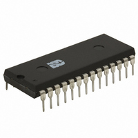
IC VOICE REC/PLAY 4-8MIN 28-DIP
Manufacturer
Nuvoton Technology Corporation of America
Series
ISD5008r
Specifications of ISD5008PY
Interface
SPI/Microwire
Filter Pass Band
1.7 ~ 3.4kHz
Duration
4 ~ 8 Min
Mounting Type
Through Hole
Package / Case
28-DIP (0.600", 15.24mm)
For Use With
ISD-ES511 - EVALUATION SYSTEM FOR ISD5100ISD-ES501 - EVALUATION SYSTEM FOR ISD5008
Lead Free Status / RoHS Status
Lead free / RoHS Compliant
Available stocks
Company
Part Number
Manufacturer
Quantity
Price
Company:

Part Number:
ISD5008PY
Manufacturer:
Nuvoton
Quantity:
226


ISD
4. Select the LOW PASS FILTER input (only) to
5. Select the SUM2 SUMMING amplifier
6. Power up the VOLUME CONTROL LEVEL—
7. Select a VOLUME CONTROL LEVEL—Bits
8. Select
9. Power up the SPEAKER amplifier and se-
and playback. These are bits D2 and D3 of
CFG1. To enable the 8.0 kHz sample rate,
D2 and D3 must be set to ZERO.
the S2 SUMMING amplifier —Bits S2M0 and
S2M1 control the state of the SUM2 SUM-
MING amplifier. These are bits D5 and D6
respectively of CFG1 and they should be
set to the state where D5 is ZERO and D6 is
ONE to select the LOW PASS FILTER (only)
path.
path through the VOLUME MUX—Bits
VLS0 and VLS1 control the state VOLUME
MUX. These bits are bits D14 and D15, re-
spectively of CFG1. They should be set to
the state where D14 is ONE and D15 is ZERO
to select the SUM2 SUMMING amplifier.
Bit VLPD controls the power-up state of the
VOLUME CONTROL attenuator. This is Bit D0
of CFG0. This bit must be set to a ZERO to
power-up the VOLUME CONTROL.
VOL0, VOL1, and VOL2 control the state of
the VOLUME CONTROL LEVEL. These are bits
D11, D12, and D13, respectively, of CFG1.
A binary count of 000 through 111 controls
the amount of attenuation through that
state. In most cases, the software will select
an attenuation level according to the de-
sires of the current users of the product. In
this example, we will assume the user wants
an attenuation of –12 dB. For that setting,
D11 should be set to ONE, D12 should be
set to ONE, and D13 should be set to a ZE-
RO.
through the OUTPUT MUX—These are bits
D3 and D4, respectively, of CFG0. They
should be set to the state where D3 is ZERO
and D4 is a ZERO to select the VOLUME
CONTROL.
lect the HIGH GAIN mode—Bits OPA0
and OPA1 control the state of the speaker
the
VOLUME
CONTROL
path
To set up the chip for Memo or Call Playback, the
configuration registers are set up as follows:
Only those portions necessary for this mode are
powered up.
(SP+ and SP–) and AUX OUT outputs. These
are bits D1 and D2 of CFG0. They must be
set to the state where D1 is ONE and D2 is
ZERO to power-up the speaker outputs in
the HIGH GAIN mode and to power-down
the AUX OUT.
CFG0=0010 0100 0010 0010 (hex 2422).
CFG1=0101 1001 1101 0001 (hex 59D1).
ISD5008 Product
25
Related parts for ISD5008PY
Image
Part Number
Description
Manufacturer
Datasheet
Request
R

Part Number:
Description:
MODULE FOR VOICE REC/PLAY 10S
Manufacturer:
Nuvoton Technology Corporation of America
Part Number:
Description:
Manufacturer:
Nuvoton Technology Corporation of America
Datasheet:
Part Number:
Description:
Manufacturer:
Nuvoton Technology Corporation of America
Datasheet:
Part Number:
Description:
Manufacturer:
Nuvoton Technology Corporation of America
Datasheet:
Part Number:
Description:
Manufacturer:
Nuvoton Technology Corporation of America
Datasheet:
Part Number:
Description:
Manufacturer:
Nuvoton Technology Corporation of America
Datasheet:
Part Number:
Description:
Manufacturer:
Nuvoton Technology Corporation of America
Datasheet: