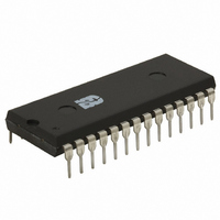
ISD5008PY Nuvoton Technology Corporation of America, ISD5008PY Datasheet - Page 6

ISD5008PY
Manufacturer Part Number
ISD5008PY
Description
IC VOICE REC/PLAY 4-8MIN 28-DIP
Manufacturer
Nuvoton Technology Corporation of America
Series
ISD5008r
Specifications of ISD5008PY
Interface
SPI/Microwire
Filter Pass Band
1.7 ~ 3.4kHz
Duration
4 ~ 8 Min
Mounting Type
Through Hole
Package / Case
28-DIP (0.600", 15.24mm)
For Use With
ISD-ES511 - EVALUATION SYSTEM FOR ISD5100ISD-ES501 - EVALUATION SYSTEM FOR ISD5008
Lead Free Status / RoHS Status
Lead free / RoHS Compliant
Available stocks
Company
Part Number
Manufacturer
Quantity
Price
Company:
Part Number:
ISD5008PY
Manufacturer:
Nuvoton
Quantity:
226
ISD5008 Product
2
2.1
SCLK
The SCLK is the clock input to the ISD5008. Gener-
ated by the master microcontroller, the SCLK syn-
chronizes data transfers in and out of the device
through the MISO and MOSI lines. Data is latched
into the ISD5008 on the rising edge of SCLK and
shifted out on the falling edge.
SS
This input, when LOW, will select the ISD5008 de-
vice.
MOSI
MOSI is the serial data input to the ISD5008 de-
vice. The master microcontroller places data to
be clocked into the ISD5008 device on the MOSI
line one-half cycle before the rising edge of SCLK.
Data is clocked into the device LSB (Least Signifi-
cant Bit) first.
MISO
MISO is the serial data output of the ISD5008 de-
vice. Data is clocked out on the falling edge of
SCLK. This output goes into a high-impedance
state when the device is not selected. Data is
clocked out of the device LSB first.
INT
INT is an open drain output pin. The ISD5008 inter-
rupt pin goes LOW and stays LOW when an Over-
flow (OVF) or End of Message (EOM) marker is
detected. Each operation that ends in an EOM or
OVF generates an interrupt, including the mes-
sage cueing cycles. The interrupt is cleared the
next time an SPI cycle is completed. The interrupt
status can be read by a RINT instruction that will
give one of the two flags out the MISO line.
2
PIN DESCRIPTIONS
DIGITAL I/O PINS
(Serial Clock)
(Slave Select)
(Master Out Slave In)
(Master In Slave Out)
(Interrupt)
OVF Flag . The overflow flag indicates that the end
of the ISD5008’s analog memory has been
reached during a record or playback operation.
EOM Flag. The end of message flag is set only
during playback, when an EOM is found. There are
eight possible EOM markers per row.
RAC
RAC is an open drain output pin that marks the
end of a row. At the 8 kHz sample frequency, the
duration of this period is 200 ms. There are 1,200
rows of memory in the ISD5008 devices. RAC stays
HIGH for 175 ms and stays LOW for the remaining
25 ms before it reaches the end of the row.
The RAC pin remains HIGH for 109.38 µsec and
stays LOW for 15.63 µsec under the Message Cue-
ing mode. See Table 15 Timing Parameters for
RAC timing information at other sample rates.
When a record command is first initiated, the RAC
pin remains HIGH for an extra T
load sample and hold circuits internal to the de-
vice. The RAC pin can be used for message man-
agement techniques.
XCLK
The external clock input for the ISD5008 product
has an internal pull-down device. Normally, the
ISD5008 is operated at one of four internal rates
selected for its internal oscillator by the Sample
Rate Select bits. If greater precision is required, the
device can be clocked through the XCLK pin as
described in Table 2.
Because the antialiasing and smoothing filters
track the Sample Rate Select bits, one must, for
optimum performance, change the external
clock AND the Sample Rate Configuration bits to
one of the four values to properly set the filters to
the correct cutoff frequency as described in Table
3. The duty cycle on the input clock is not critical,
as the clock is immediately divided by two inter-
nally. If the XCLK is not used, this input should be
connected to V
(Row Address Clock)
(External Clock Input)
SSD
.
Voice Solutions in Silicon
RACLO
period, to
™


