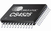
CS4525-CNZ Cirrus Logic Inc, CS4525-CNZ Datasheet - Page 84

CS4525-CNZ
Manufacturer Part Number
CS4525-CNZ
Description
IC AMP AUDIO PWR 30W QUAD 48QFN
Manufacturer
Cirrus Logic Inc
Series
Popguard®r
Type
Class Dr
Datasheet
1.CS4525-CNZ.pdf
(98 pages)
Specifications of CS4525-CNZ
Output Type
2-Channel (Stereo) or 4-Channel (Quad)
Package / Case
48-QFN
Max Output Power X Channels @ Load
30W x 1 @ 4 Ohm; 15W x 2 @ 8 Ohm
Voltage - Supply
8 V ~ 18 V
Features
ADC, Depop, I²C, I²S, Mute, PWM, Short-Circuit and Thermal Protection, Volume Control
Mounting Type
Surface Mount
Product
Class-D
Output Power
30 W
Thd Plus Noise
10 %
Operating Supply Voltage
2.5 V to 5 V
Supply Current
54 mA
Maximum Power Dissipation
180 mW
Maximum Operating Temperature
+ 70 C
Mounting Style
SMD/SMT
Audio - Load Impedance
4 Ohms, 6 Ohms, 8 Ohms
Audio Load Resistance
8 Ohms, 4 Ohms
Minimum Operating Temperature
0 C
Supply Voltage (max)
5.25 V
Supply Voltage (min)
2.375 V
Amplifier Class
D
No. Of Channels
4
Supply Voltage Range
8V To 18V
Load Impedance
4ohm
Operating Temperature Range
0°C To +70°C
Amplifier Case Style
QFN
No. Of Pins
48
Rohs Compliant
Yes
Lead Free Status / RoHS Status
Lead free / RoHS Compliant
For Use With
598-1586 - REFERENCE BOARD FOR CS4525 PWM
Lead Free Status / Rohs Status
Lead free / RoHS Compliant
Other names
598-1264
Available stocks
Company
Part Number
Manufacturer
Quantity
Price
Company:
Part Number:
CS4525-CNZ
Manufacturer:
CRYSTAL
Quantity:
329
Part Number:
CS4525-CNZ
Manufacturer:
TI/德州仪器
Quantity:
20 000
Part Number:
CS4525-CNZR
Manufacturer:
CIRRUSLOGICINC
Quantity:
20 000
84
9.15
9.15.1 ADC Invert Signal Polarity (InvADC)
9.15.2 Invert Channel PWM Signal Polarity (InvChX)
9.15.3 Invert Sub PWM Signal Polarity (InvSub)
9.15.4 ADC Channel Mute (MuteADC)
9.15.5 Independent Channel A & B Mute (MuteChX)
InvADC
7
Mute/Invert Control (Address 5Bh)
Default = 0
Function:
When set, the signal polarity of the ADC will be inverted.
Default = 0
Function:
When set, the respective channel’s power and logic-level PWM output signal polarity will be inverted. The
serial output on the auxiliary and delay ports are unaffected.
Default = 0
Function:
When set, the Sub channel’s power and logic-level PWM output polarity will be inverted. The serial output
on the auxiliary port is unaffected.
Default = 0
Function:
The output of the ADC will mute when enabled.
Default = 0
Function:
The respective channel’s power PWM, logic-level PWM, and auxiliary serial data outputs will enter a mute
state when enabled. The delay serial output will be unaffected if the delay port is enabled. The muting
InvADC Setting
InvChX Setting
InvSub Setting
MuteADC Setting
0 .......................................... ADC signal polarity not inverted.
1 .......................................... ADC signal polarity inverted.
0 .......................................... Channel X PWM signal polarity not inverted.
1 .......................................... Channel X PWM signal polarity inverted.
0 .......................................... Sub channel PWM signal polarity not inverted.
1 .......................................... Sub channel PWM signal polarity inverted.
0 .......................................... ADC un-muted.
1 .......................................... ADC muted.
InvSub
6
InvCh2
ADC Signal Inversion State
Channel X PWM Signal Inversion State
Sub Channel PWM Signal Inversion State
ADC Mute State
5
InvCh1
4
MuteADC
3
MuteSub
2
MuteChB
1
CS4525
MuteChA
DS726PP2
0


