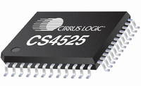
CS4525-CNZ Cirrus Logic Inc, CS4525-CNZ Datasheet - Page 89

CS4525-CNZ
Manufacturer Part Number
CS4525-CNZ
Description
IC AMP AUDIO PWR 30W QUAD 48QFN
Manufacturer
Cirrus Logic Inc
Series
Popguard®r
Type
Class Dr
Datasheet
1.CS4525-CNZ.pdf
(98 pages)
Specifications of CS4525-CNZ
Output Type
2-Channel (Stereo) or 4-Channel (Quad)
Package / Case
48-QFN
Max Output Power X Channels @ Load
30W x 1 @ 4 Ohm; 15W x 2 @ 8 Ohm
Voltage - Supply
8 V ~ 18 V
Features
ADC, Depop, I²C, I²S, Mute, PWM, Short-Circuit and Thermal Protection, Volume Control
Mounting Type
Surface Mount
Product
Class-D
Output Power
30 W
Thd Plus Noise
10 %
Operating Supply Voltage
2.5 V to 5 V
Supply Current
54 mA
Maximum Power Dissipation
180 mW
Maximum Operating Temperature
+ 70 C
Mounting Style
SMD/SMT
Audio - Load Impedance
4 Ohms, 6 Ohms, 8 Ohms
Audio Load Resistance
8 Ohms, 4 Ohms
Minimum Operating Temperature
0 C
Supply Voltage (max)
5.25 V
Supply Voltage (min)
2.375 V
Amplifier Class
D
No. Of Channels
4
Supply Voltage Range
8V To 18V
Load Impedance
4ohm
Operating Temperature Range
0°C To +70°C
Amplifier Case Style
QFN
No. Of Pins
48
Rohs Compliant
Yes
Lead Free Status / RoHS Status
Lead free / RoHS Compliant
For Use With
598-1586 - REFERENCE BOARD FOR CS4525 PWM
Lead Free Status / Rohs Status
Lead free / RoHS Compliant
Other names
598-1264
Available stocks
Company
Part Number
Manufacturer
Quantity
Price
Company:
Part Number:
CS4525-CNZ
Manufacturer:
CRYSTAL
Quantity:
329
Part Number:
CS4525-CNZ
Manufacturer:
TI/德州仪器
Quantity:
20 000
Part Number:
CS4525-CNZR
Manufacturer:
CIRRUSLOGICINC
Quantity:
20 000
DS726PP2
9.19.6 Power Down (PDnAll)
9.20
Bits [7:4] in this register are read only. A ‘1’b in these bit positions indicates that the associated condition has oc-
curred at least once since the register was last read. A ‘0’b indicates that the associated condition has not occurred
since the last reading of the register. Reading the register resets bits to [7:4] ‘0’b. These bits are considered “edge-
triggered” events. The operation of these 4 bits is not affected by the interrupt mask bits and the condition of each
bit can be polled instead of generating an interrupt as required.
9.20.1 SRC Lock State Transition Interrupt (SRCLock)
SRCLock
7
Interrupt (Address 60h)
the channel output configuration selected. When transitioning from normal operation to power down, the
specific output will power down according to the state of the RmpSpd[1:0] bits and the channel output con-
figuration selected.
The entire divide will enter a low-power state when this function is enabled:
Default = 1
Function:
The CS4525 will enter a power-down state when this function is enabled:
1. The power PWM outputs will be held in a high-impedance state.
2. The logic-level PWM outputs will continuously drive a logic ‘0’ if the HiZPSig bit is set and will be held
3. AUX_SDOUT, the auxiliary serial data output, will be driven to a digital-low. AUX_LRCK and
4. DLY_SDOUT, the delay serial data output, will output the unprocessed audio data from SDATA if
The contents of the control registers are retained in this state. Once the PDnAll bit is disabled, the pow-
ered and logic-level PWM outputs will first perform a click-free start-up function and then resume normal
operation.
The PDnAll bit defaults to ‘enabled’ on power-up and must be disabled before normal operation can occur.
Function:
This bit is read only. When set, indicates that the SRC has transitioned from an unlock to lock state or
from a lock state to an unlock state since the last read of this register. Conditions which cause the SRC
to transition states, such as loss of LRCK, SCLK, an LRCK ratio change, or the SRC achieving lock, will
PDnChX Setting
PDnAll Setting
0 ..........................................Normal power output X operation.
1 ..........................................Power output X power-down enabled.
0 ..........................................Normal device operation.
1 ..........................................Device power-down enabled.
in a high-impedance state if the HiZPSig bit is clear.
AUX_SCLK, the auxiliary serial output’s clocks, will continue to operate if the EnAuxPort bit is set,
ADC/SP is cleared, and the serial audio input receives a valid SCLK and LRCK; otherwise they will
also be driven to a digital-low voltage.
EnAuxPort is set, DlyPortCfg[1:0] is configured for serial output delay interface, ADC/SP is cleared,
and the serial audio input port receives a valid SCLK, LRCK, and SDATA. Otherwise, it will drive a
low voltage.
ADCOvfl
6
Power Output X Power-Down State
Device Power-Down State
ChOvfl
5
AmpErr
4
SRCStateM
3
ADCOvflM
2
ChOvflM
1
AmpErrM
CS4525
0
89


