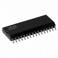
TDA8932BT/N2,112 NXP Semiconductors, TDA8932BT/N2,112 Datasheet - Page 24

TDA8932BT/N2,112
Manufacturer Part Number
TDA8932BT/N2,112
Description
IC AMP AUDIO 55W STER D 32SOIC
Manufacturer
NXP Semiconductors
Type
Class Dr
Datasheet
1.TDA8932BTWN2118.pdf
(48 pages)
Specifications of TDA8932BT/N2,112
Output Type
1-Channel (Mono) or 2-Channel (Stereo)
Package / Case
32-SOIC (7.5mm Width)
Max Output Power X Channels @ Load
55W x 1 @ 8 Ohm; 26.5W x 2 @ 4 Ohm
Voltage - Supply
10 V ~ 36 V, ±5 V ~ 18 V
Features
Depop, Differential Inputs, Mute, Short-Circuit and Thermal Protection
Mounting Type
Surface Mount
Product
Class-D
Output Power
55 W
Available Set Gain
36 dB
Common Mode Rejection Ratio (min)
75 dB
Thd Plus Noise
0.007 %
Operating Supply Voltage
22 V
Supply Current
145 mA
Maximum Power Dissipation
5000 mW
Maximum Operating Temperature
+ 85 C
Mounting Style
SMD/SMT
Audio Load Resistance
8 Ohms
Dual Supply Voltage
+/- 11 V
Input Signal Type
Differential
Minimum Operating Temperature
- 40 C
Output Signal Type
Differential, Single
Supply Type
Single or Dual
Supply Voltage (max)
36 V
Supply Voltage (min)
10 V
Lead Free Status / RoHS Status
Lead free / RoHS Compliant
Other names
935283477112
TDA8932BT
TDA8932BT
TDA8932BT
TDA8932BT
NXP Semiconductors
TDA8932B_4
Product data sheet
14.2 Output current limiting
14.3 Speaker configuration and impedance
14.4 Single-ended capacitor
The peak output current I
normal operation the output current should not exceed this threshold level of 4 A
otherwise the output signal is distorted. The peak output current in SE or BTL
configurations can be estimated using
SE configuration:
BTL configuration:
Where:
Example:
A 4
running into current limiting. Current limiting (clipping) will avoid audio holes but it causes
a comparable distortion like voltage clipping.
For a flat frequency response (second-order Butterworth filter) it is necessary to change
the low-pass filter components Llc and Clc according to the speaker configuration and
impedance.
Table 14.
The SE capacitor forms a high-pass filter with the speaker impedance. So the frequency
response will roll-off with 20 dB per decade below f
I
I
Configuration
SE
BTL
O max
O max
V
R
R
R
R
P
L
DSon
s
ESR
= series resistance output inductor ( )
= supply voltage V
= load impedance ( )
speaker in the BTL configuration can be used up to a supply voltage of 18 V without
= equivalent series resistance SE capacitor ( )
= on-resistance power switch ( )
----------------------------------------------------------
R
----------------------------------------------------- -
R
Filter component values
L
L
Table 14
+
+
R
2
DSon
0.5 V
V
R
P
DSon
+
Rev. 04 — 18 December 2008
shows the practical required values.
R
R
4
6
8
4
6
8
P
DDP1
s
L
O(max)
+
+
( )
R
R
s
ESR
V
is internally limited above a level of 4 A (minimum). During
4 A
SSP1
4 A
(V) or V
Equation 5
DDP2
Llc ( H)
22
33
47
10
15
22
and
-3dB
V
SSP2
Equation
(3 dB cut-off frequency).
(V)
6.
Class-D audio amplifier
TDA8932B
Clc (nF)
680
470
330
1500
1000
680
© NXP B.V. 2008. All rights reserved.
24 of 48
(5)
(6)


