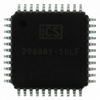
ICS2008BY-10LF IDT, Integrated Device Technology Inc, ICS2008BY-10LF Datasheet - Page 22

ICS2008BY-10LF
Manufacturer Part Number
ICS2008BY-10LF
Description
IC TIME CODE RCVR/GEN 44-TQFP
Manufacturer
IDT, Integrated Device Technology Inc
Type
SMPTE Time Code Receiver, Generatorr
Datasheet
1.ICS2008BY-10LF.pdf
(22 pages)
Specifications of ICS2008BY-10LF
Applications
Multimedia
Mounting Type
Surface Mount
Package / Case
44-TQFP, 44-VQFP
Operating Supply Voltage (typ)
5V
Operating Supply Voltage (min)
4.5V
Operating Supply Voltage (max)
5.5V
Operating Temp Range
0C to 70C
Operating Temperature Classification
Commercial
Mounting
Surface Mount
Pin Count
44
Lead Free Status / RoHS Status
Lead free / RoHS Compliant
Other names
2008BY-10LF
800-1026
800-1026
Available stocks
Company
Part Number
Manufacturer
Quantity
Price
Company:
Part Number:
ICS2008BY-10LF
Manufacturer:
MP
Quantity:
101
Company:
Part Number:
ICS2008BY-10LF
Manufacturer:
IDT, Integrated Device Technology Inc
Quantity:
10 000
Company:
Part Number:
ICS2008BY-10LFT
Manufacturer:
IDT, Integrated Device Technology Inc
Quantity:
10 000
AC coupling is not recommended when the input is of large voltage swing and/or of low
frequency. If AC coupling is attempted in these cases, then great care must be taken that
the voltage at the input pin does not go below ground nor be allowed to settle near the
threshold value. In such cases, it is recommended that the input pin in question be
observed in operation with a high-impedance scope probe.
In the case of large voltage swing inputs, the ICS2008B input pin can easily be driven
below ground. This is possible because the voltage at the pin will swing around the
internally generated bias point. Driving the input pin below ground should never be
allowed and can potentially damage the device. In the case of a large input swing, a series
resistor can be placed between the coupling capacitor and the input pin to divide down
the input voltage and reduce the swing at the input pin.
In the case of low frequency signals, the coupling capacitor can become fully charged
which will allow the input slew to close to its threshold value, causing any noise to
falsely trigger the input. Low duty cycle inputs can have an effect similar to low
frequency. A larger coupling capacitor may be required. The case of a low frequency,
large amplitude input is especially dangerous because the voltage swing at the input pin is
increased by the same amount that the capacitor has charged.
As an example of the measures that may need to be taken, a 5V, 30 Hz, 50% duty cycle
signal on the Click input can be safely AC coupled to the Click pin by using a 1µF
coupling capacitor and a 100K ohm series resistor. The large time constant prevents the
capacitor from becoming fully charged and the series resistor, combined with the internal
resistor, divides down the input voltage to an acceptable swing so that the input pin is
never driven below ground.
1. Figure 8 “Self Biased Inputs” Diagram on page 15:
2. Add the following notes called “AC Coupling of Internally-Biased Inputs” after
“Self Biased Inputs” section on page 15.
a) VDD/2 should be VDD/3
b) 5K should be 35K
ICS2008B Errata


