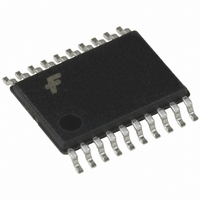
74VHC244MTCX Fairchild Semiconductor, 74VHC244MTCX Datasheet - Page 4

74VHC244MTCX
Manufacturer Part Number
74VHC244MTCX
Description
IC BUFF/DVR TRI-ST DUAL 20TSSOP
Manufacturer
Fairchild Semiconductor
Series
74VHCr
Specifications of 74VHC244MTCX
Logic Type
Buffer/Line Driver, Non-Inverting
Number Of Elements
2
Number Of Bits Per Element
4
Current - Output High, Low
8mA, 8mA
Voltage - Supply
2 V ~ 5.5 V
Operating Temperature
-40°C ~ 85°C
Mounting Type
Surface Mount
Package / Case
20-TSSOP
Logic Family
VHC
Number Of Channels Per Chip
8
Polarity
Non-Inverting
Supply Voltage (max)
5.5 V
Supply Voltage (min)
2 V
Maximum Operating Temperature
+ 85 C
Mounting Style
SMD/SMT
High Level Output Current
- 8 mA
Low Level Output Current
8 mA
Minimum Operating Temperature
- 40 C
Number Of Lines (input / Output)
8 / 8
Output Type
3-State
Propagation Delay Time
11.9 ns at 3.3 V, 7.5 ns at 5 V
Logical Function
Buffer/Line Driver
Number Of Elements
2
Number Of Channels
8
Number Of Inputs
8
Number Of Outputs
8
Operating Supply Voltage (typ)
2.5/3.3/5V
Package Type
TSSOP
Operating Supply Voltage (max)
5.5V
Operating Supply Voltage (min)
2V
Quiescent Current
4uA
Technology
CMOS
Pin Count
20
Mounting
Surface Mount
Operating Temp Range
-40C to 85C
Operating Temperature Classification
Industrial
Logic Device Type
Buffer, Non Inverting
Supply Voltage Range
2V To 5.5V
Logic Case Style
TSSOP
No. Of Pins
20
Operating Temperature Range
-40°C To +85°C
Family Type
VHC
Rohs Compliant
Yes
Lead Free Status / RoHS Status
Lead free / RoHS Compliant
Other names
74VHC244MTCXTR
Available stocks
Company
Part Number
Manufacturer
Quantity
Price
Company:
Part Number:
74VHC244MTCX
Manufacturer:
FAIR
Quantity:
2 421
Company:
Part Number:
74VHC244MTCX
Manufacturer:
FAI
Quantity:
194
Company:
Part Number:
74VHC244MTCX
Manufacturer:
Fairchild
Quantity:
3 490
Part Number:
74VHC244MTCX
Manufacturer:
FAIRCHILD/仙童
Quantity:
20 000
www.fairchildsemi.com
t
t
t
t
t
t
t
t
C
C
C
PLH
PHL
PZL
PZH
PLZ
PHZ
OSLH
OSHL
AC Electrical Characteristics
Note 4: Parameter guaranteed by design. t
Note 5: C
operating current can be obtained by the equation: I
IN
OUT
PD
Symbol
PD
is defined as the value of the internal equivalent capacitance which is calculated from the operating current consumption without load. Average
Propagation Delay
Time
3-STATE Output
Enable Time
3-STATE Output
Disable Time
Output to Output
Skew
Input Capacitance
Output Capacitance
Power Dissipation Capacitance
Parameter
OSLH
3.3
5.0
3.3
5.0
3.3
5.0
3.3
5.0
|t
PLHmax
CC
V
(V)
r
r
r
r
r
r
r
r
CC
(OPR.)
0.3
0.5
0.3
0.5
0.3
0.5
0.3
0.5
t
PLHmin
Min
C
PD
|; t
* V
OSHL
CC
T
A
* f
10.3
Typ
5.8
8.3
3.9
5.4
6.6
9.1
4.7
6.2
6.7
19
IN
4
6
|t
4
25
PHLmax
q
I
C
CC
/8 (per bit).
Max
10.6
14.1
14.0
11.9
t
8.4
5.5
7.5
7.3
9.3
9.2
1.5
1.0
PHLmin
10
|.
T
A
Min
1.0
1.0
1.0
1.0
1.0
1.0
1.0
1.0
1.0
1.0
40
q
C to
Max
10.0
13.5
12.5
16.0
10.5
16.0
10.5
6.5
8.5
8.5
1.5
1.0
10
85
q
C
Units
ns
ns
ns
ns
ns
ns
pF
pF
pF
R
R
(Note 4)
V
V
(Note 5)
CC
CC
L
L
1 k
1 k
Conditions
Open
5.0V
:
:
C
C
C
C
C
C
C
C
C
C
C
C
L
L
L
L
L
L
L
L
L
L
L
L
15 pF
50 pF
15 pF
50 pF
15 pF
50 pF
15 pF
50 pF
50 pF
50 pF
50 pF
50 pF


